

You are using an out of date browser. It may not display this or other websites correctly.
You should upgrade or use an alternative browser.
You should upgrade or use an alternative browser.
DOHC Daily Driver.
- Thread starter danm
- Start date
I forgot that-but then again the 75 is not a real rover to me-in my opinion anyway for what thats worth--I remember the time here when that was being made--not good times-now factory owned by germans with most employees from eastern europe making a so called icon--which is almost the size of a p6 anyway--yet very ugly -- funny that every new update makes it uglier--not the p6-nice modern looks even today 50 yrs later
colnerov
Well-Known Member
symes said:better a ford than bmw eh - considering what happened to rover
BMW didn't get away scot free, it nearly crippled them and I think more than one executive
had to fall on his sword, I know it's nothing to be proud of. But they thought they could come
along buy the company take/use the small car and four wheel drive technology, which they
had no experience of, and move on. The rest as they say is history including selling Land
Rover to Ford.
Colin
danm
Member
Hi I did wonder if it would be a contentious subject, Ford engine in a Rover 
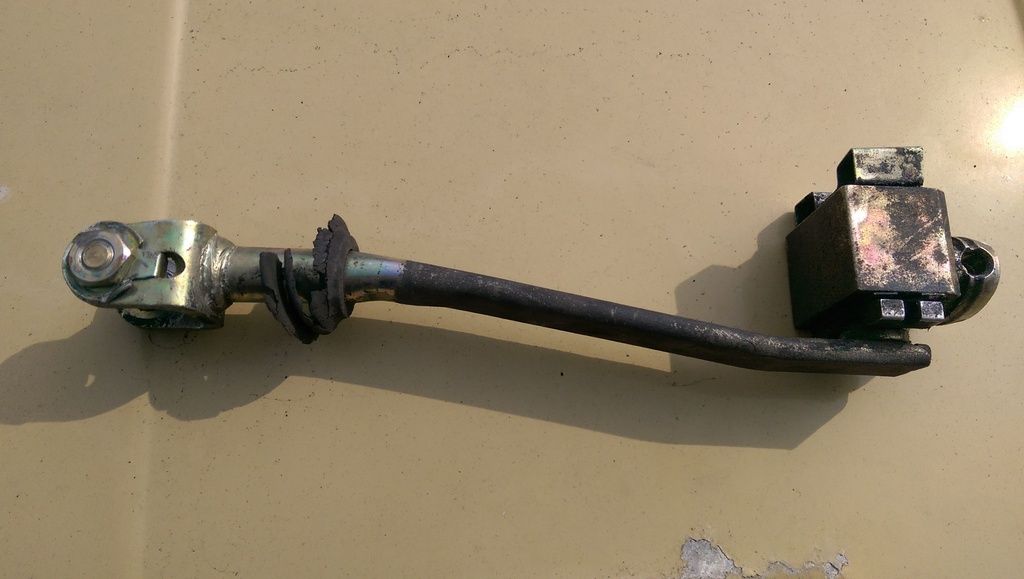
Up next for the chop is the remote linkage. It is too long as it is and possibly too high as well. It is made from pressed steel so will be relatively easy to alter.
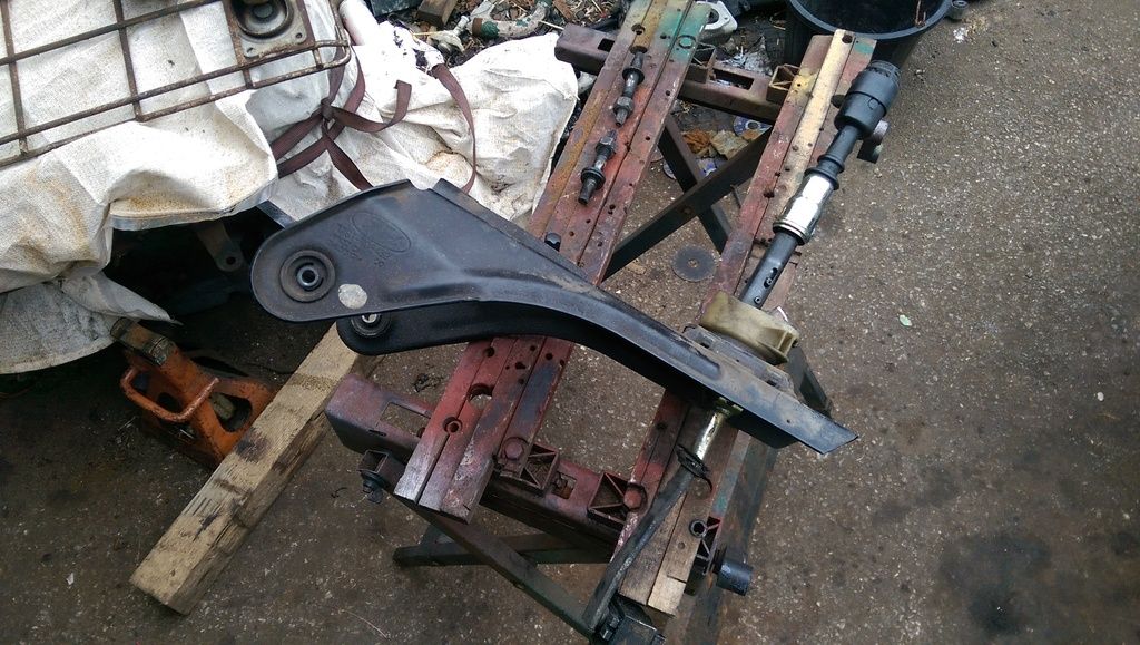
The gear lever is both too long and hideous to look at!
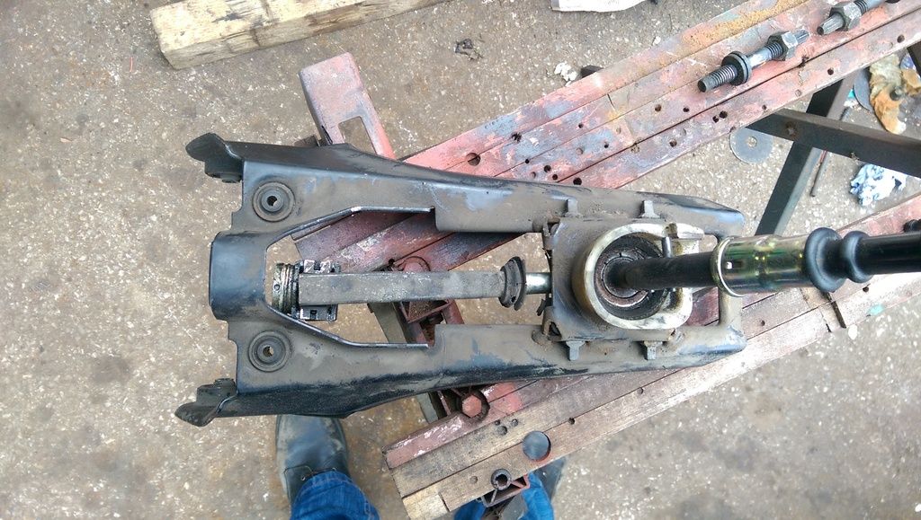
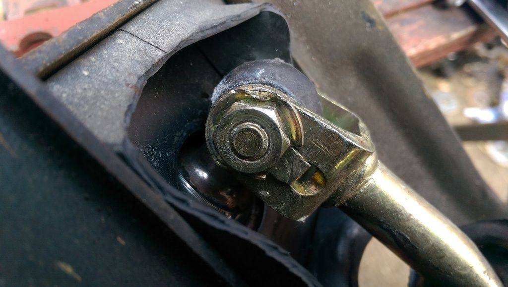
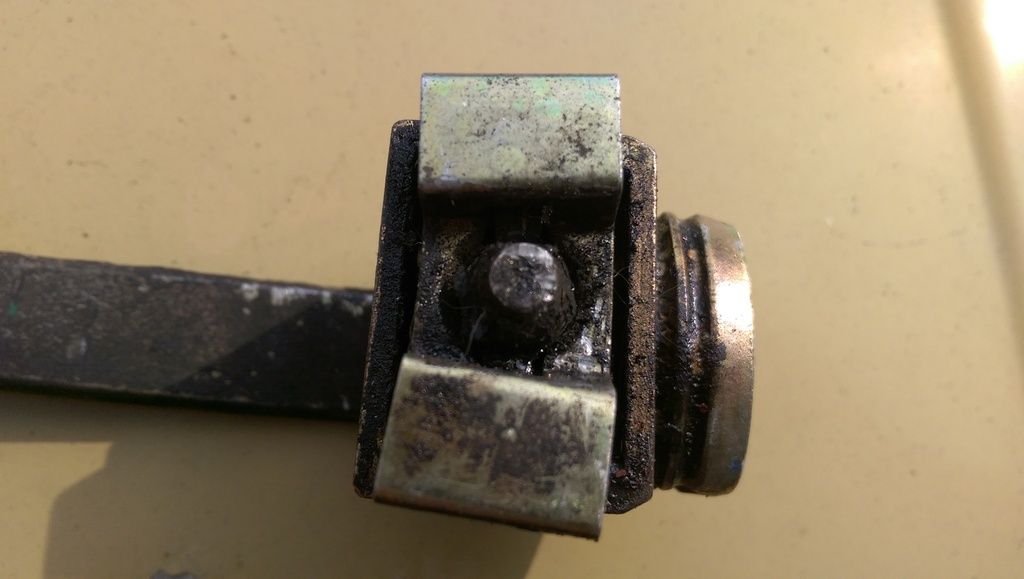
It is attatched to the transmission by two bolts at the side and a pair of pins through the top rubber bushes. The linkage is connected to the selector rod with a ball joint and pin, this arrangement should hopfully allow a degree of freedom with the positioning and alignment.
The four rubber bushes can be seen here.

The actual rod in the linkage is basically a flattened steel tube, this could be bolted back together or most likely I will weld it.
Weather and time permitting I hope to have this underway or maybe even finished tomorrow.
Dan
Up next for the chop is the remote linkage. It is too long as it is and possibly too high as well. It is made from pressed steel so will be relatively easy to alter.
The gear lever is both too long and hideous to look at!
It is attatched to the transmission by two bolts at the side and a pair of pins through the top rubber bushes. The linkage is connected to the selector rod with a ball joint and pin, this arrangement should hopfully allow a degree of freedom with the positioning and alignment.
The four rubber bushes can be seen here.
The actual rod in the linkage is basically a flattened steel tube, this could be bolted back together or most likely I will weld it.
Weather and time permitting I hope to have this underway or maybe even finished tomorrow.
Dan
danm
Member
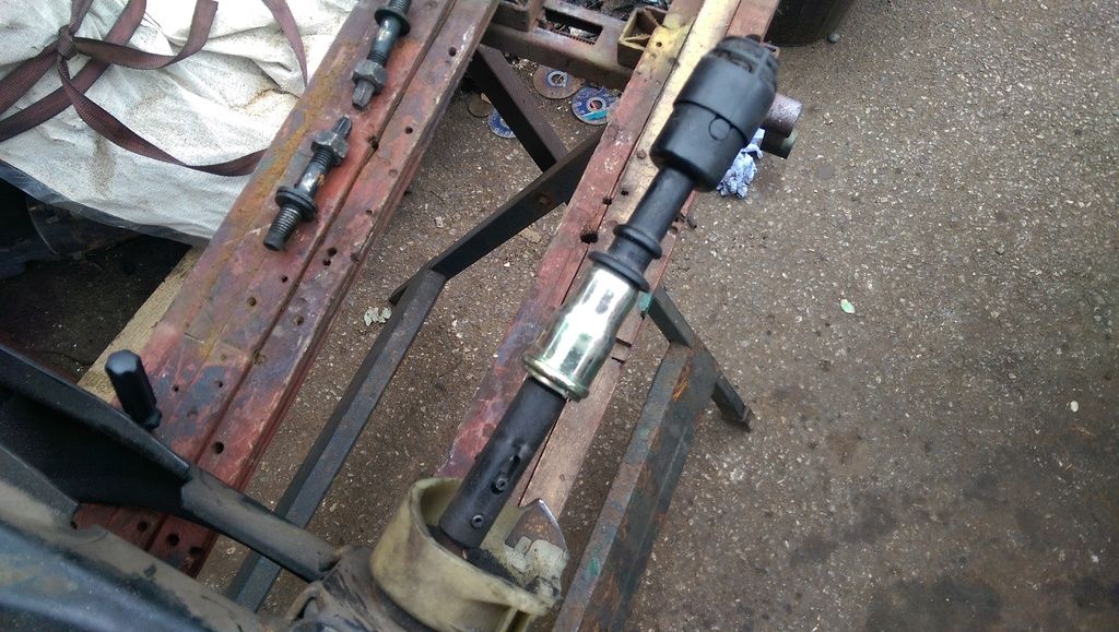
Hi, I have made a start on modifying the remote gear linkage. The first job was to remove the selector rod from the base of the lever.
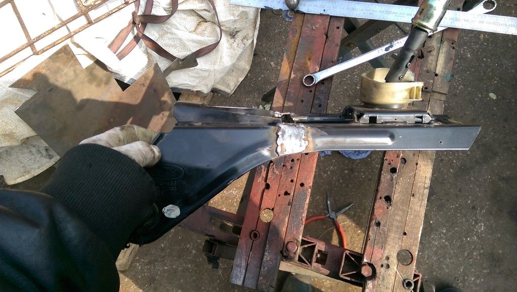
I then cut the remote in half and fitted the front section to the back of the gearbox so that I could determine how much would have to be chopped out........Only that no metal had to be chopped out at all....
the stock remote was actually too short! I couldn't believe it, I had assumed that it would be at least two inches too long but in the end it turned out to be 12mm too short.
The extension was soon welded in.
I have got to do the selector rod but I ran out of time this morning, I have also got to somehow extricate the selector rods pin from the rubber bush that should be fitted to the back of the box. It should just be a case of pressing in the spring loaded clip on each side but mine has rusted in solid!
I will hopefully extend the rod too if I get the time tonight.
One job that I am in the process of doing is a servo rebuild. I will not bore people with whats what with this as I'm sure it has already been covered at length somewhere else on here. Despite the servo seemingly
working without fault there was a large quantity of fluid inside the vacuum section, I'd say it was full almost to the vacuum connection. It must have been like this for years as I have not had to top up the fluid since I have been using the car, the level had dropped very little in that time. Hopefully, it will remain dry in there from now on as the cylinder and operating rod are in good order.....as is the diaphragm.
Dan
cooper1203
Member
are u going to take it to the quart pot when ur done. seem to remember lots of saxo type teenagers hanging around in the car park when I drove past on my way home on a sunday night. would be good to show them what a real mechanic can do rather than just bolting on lights and an air filter
coop
coop
danm
Member
cooper1203 said:are u going to take it to the quart pot when ur done. seem to remember lots of saxo type teenagers hanging around in the car park when I drove past on my way home on a sunday night. would be good to show them what a real mechanic can do rather than just bolting on lights and an air filter
coop
I guess I could do
I remember having a little chav roar up my behind in a Saxo some time ago. I was in an Austin Allegro and he thought it would be funny to intimidate the guy in the old car. What he didn't know was that the Allegro was a 1750 running a gas flowed head and twin Webber 40's along with a modern ignition system and decent exhaust. I only wish that I could have seen his face as the Austin squatted right down at the back as I opened those Webbers up and blew the doors off his French folly! Funnily enough, I didn't see him again. I later went on to fit an Eaton M45 supercharger to it, it was absolutely ballistic but the clutch could not take the torque and used to slip as the boost came in. I figured that if I somehow managed to find an uprated clutch I would just end up breaking the next weakest link in the transmission. :cry: Dan
danm
Member
colnerov said:Hi, I do like a "Q" car. I've built a couple in my time. Good fun.
Colin
I agree, there is nothing better than surprising someone driving a chav wagon in a stock looking classic, that said, I do not think that my engine conversion will make my Rover much of a Q car.
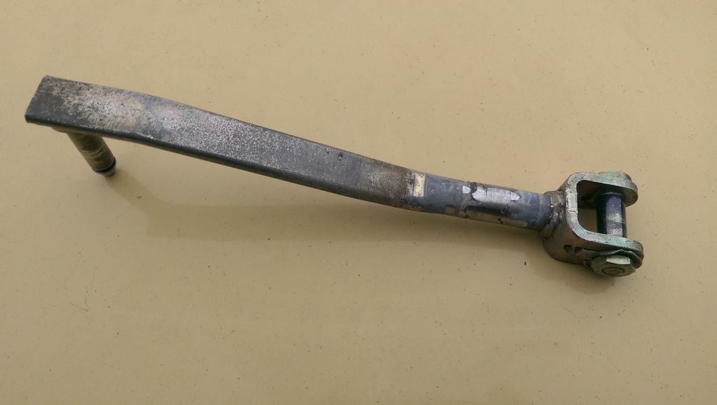
I have now finished modifying the gear change remote, the, the selector rod was indeed hollow with the void being just over 8mm in diameter. This made extending it a bit easier as it allowed me to base the extension on an M8 bolt. The rod was cut, the bolt shank inserted and then welded. I built the weld up level with the original rod. Here is the final result.
I have also replaced the original output flange. The original setup was for use with a Guibo joint. Not only was the supplied one knackred but I'm sure that it would not work with with the standard prop so it had to go.
The gearbox came with this mass damper fitted to the output flange, it would not fit between the gearbox mounts and would not have worked with the new prop flange.
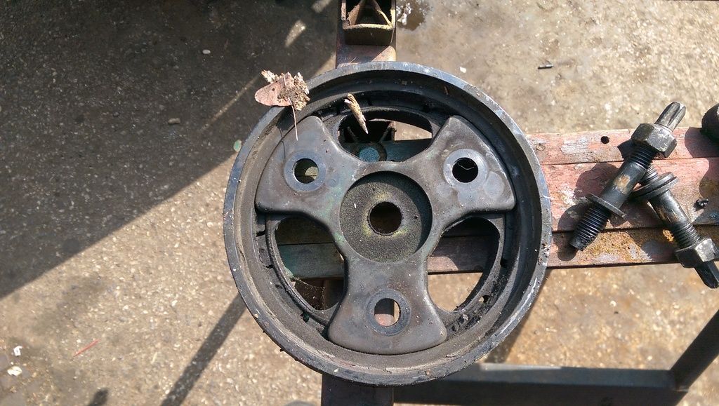
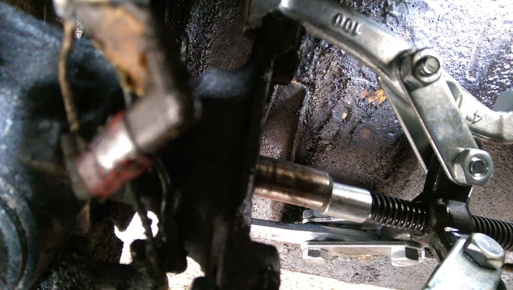
I have removed the old flange, it needed a puller to remove but once it started moving, it came off easily.
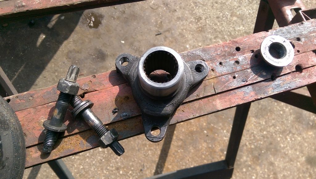
The new drive flange is now fitted and I have spoken to the company who are going to modify my propshaft. I am using a company in Romford called Dynoprop, I have used them before and can heartily recommend them for any prop related work. My shaft will be going in on Tuseday and hopfully will be ready early next week.
One thing that did surprise me was that once I had removed the front section of the prop from the gearbox was that the UJ was knackred the bearing cups feel like that they have suffered bad brinelling and are now useless. I am now wondering weather the front UJ was the thing that made my gear lever tizz like mad between 65 and 70 mph. Suffice to say that said worn parts will all be thrown in the bin!!!!
Dan
danm
Member
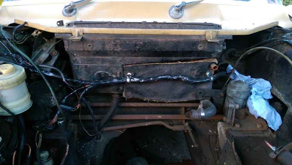
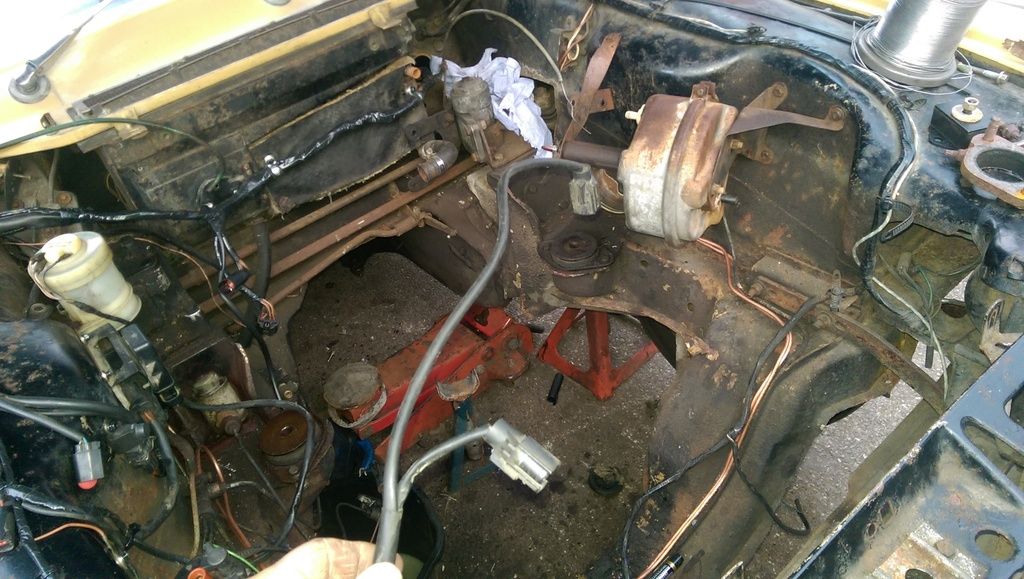
Hi, Now that I have determined the length of the propshaft I have pulled the engine and box back out to allow me to fit the various sensors and modules and to run new brake pipes to the repositioned servo. The servo is now in the mirror opposite position to where it was originally mounted, this was achieved using the original brackets flipped over. Both needed a slight tweak to fit but the servo had a spare stud that is now in the perfect position for the LH mounting position. I hope to measure up and obtain the new longer brake pipes tomorrow.
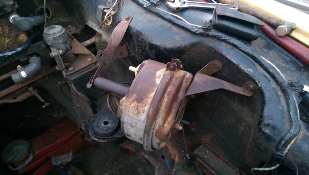
The new pipes will follow the NSF pipe routing across the top of the cross member.
Dan
The new pipes will follow the NSF pipe routing across the top of the cross member.
Dan
colnerov
Well-Known Member
Hi, the usual orientation of the servo is with the air valve uppermost or at least above the
centreline. I don't think there is any real reason to do with the operation of it, but if you get
the brakes dragging it's the air valve and can be changed in situ. With pointing down like you
have done it would need removal. So some thing to consider, could you rotate it if needed?
Colin
centreline. I don't think there is any real reason to do with the operation of it, but if you get
the brakes dragging it's the air valve and can be changed in situ. With pointing down like you
have done it would need removal. So some thing to consider, could you rotate it if needed?
Colin
danm
Member
Hi Colin, I agree that having it on top would make servicing it easier but I have mounted it at near enough the same angle/ position as it was originally. I have fitted an overhaul kit to it so all being well I shouldn't have to touch it again for quite some time.................unless I've just jinxed it by saying that!!!!!
Dan
Dan
danm
Member
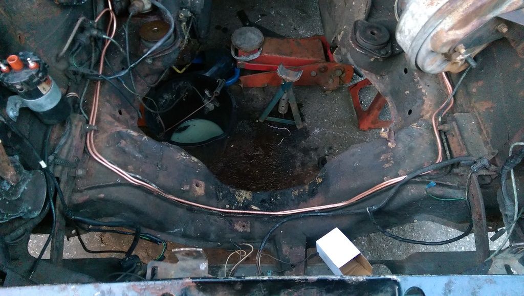
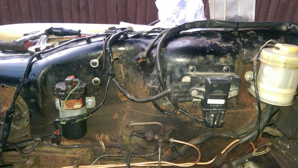
Hi, Today I have made reasonable progress in the preparation of the engine bay. I have now mounted the important modules and sensors for the new engine and plumbed in the repositioned servo, although I still need to retain the new pipework.
Here is a general view of the new brake pipes.
The very important ignition amplifier or TFI module as Ford call it with the MAP sensor mounted in front.
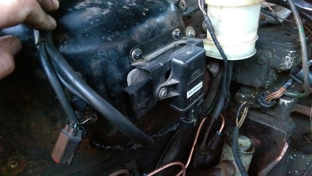
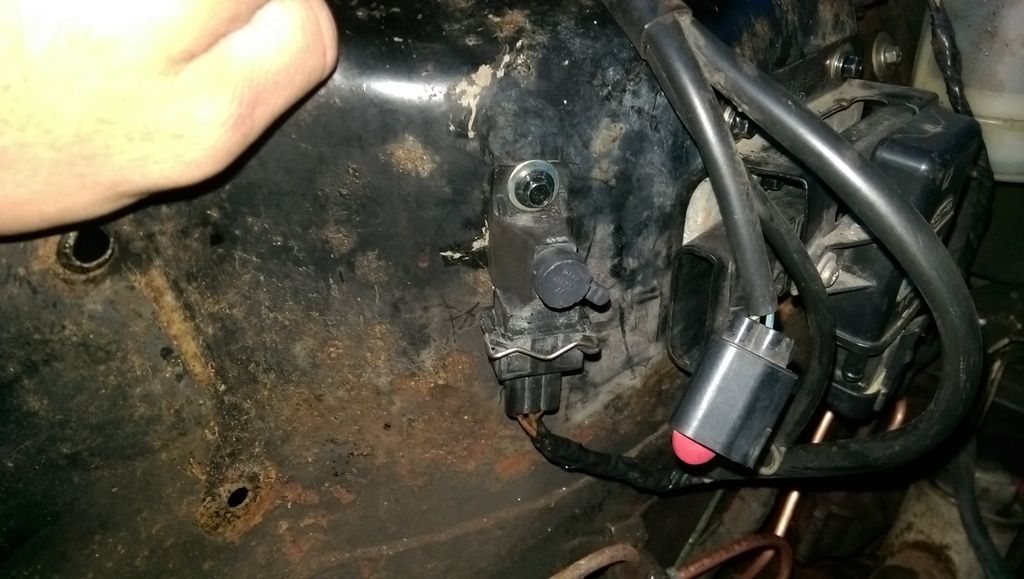
This little unit is the CO potentiometer for adjusting the idle mixture.
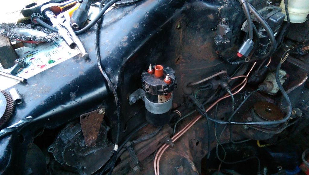
I have mounted the coil further forward so it is closer to the front mounted distributor.
The main loom has been "P" clipped to the heater box.
Tomorrow I intend to extend the fan wiring and remove the excess from the ignition loom, there is several feet that need removing here.
Dan
Here is a general view of the new brake pipes.
The very important ignition amplifier or TFI module as Ford call it with the MAP sensor mounted in front.
This little unit is the CO potentiometer for adjusting the idle mixture.
I have mounted the coil further forward so it is closer to the front mounted distributor.
The main loom has been "P" clipped to the heater box.
Tomorrow I intend to extend the fan wiring and remove the excess from the ignition loom, there is several feet that need removing here.
Dan
cooper1203
Member
hi there, great work wish I had the skills to take on a project like that but im afraid if it isn't in the Haynes manual im knackered. May I ask where u get your brake pipe from pls.
many thanks
coop
many thanks
coop
danm
Member
Hi Coop, thanks for that.
I got the brake pipes from a local car spares shop, it is a small independent one like what used to be everywhere. They are really good in that I took my old pipes in and so they could get the right ends and they made them up to the length that I specified in five minutes!
Dan
I got the brake pipes from a local car spares shop, it is a small independent one like what used to be everywhere. They are really good in that I took my old pipes in and so they could get the right ends and they made them up to the length that I specified in five minutes!
Dan
Willy Eckerslyke
Well-Known Member
Seeing that last photo, I'd recommend checking the grommet where the accelerator rod passes through the bulkhead and replacing it if it's not perfect. Easy job to do when the engine's out, but a real pain otherwise.
danm
Member
Willy Eckerslyke said:Seeing that last photo, I'd recommend checking the grommet where the accelerator rod passes through the bulkhead and replacing it if it's not perfect. Easy job to do when the engine's out, but a real pain otherwise.
That is a good suggestion and I have one on order, I need to strip the throttle pedal out in order to adapt it for cable operation so I would be an absolute Muppet not to replace it.
I have near enough finished the wiring under the bonnet now. Only the washer pump, alternator and starter are left to do and I need the engine back in for that.
I have removed the excess from the ignition circuit and I have extended the fan wiring so that it now reaches down to the radiator. There is provision there for two fans, initially I will only be running one but it is nice to know that I can increase the number if needed.
Here is how I have left it tonight, it looks a bit tidier now...
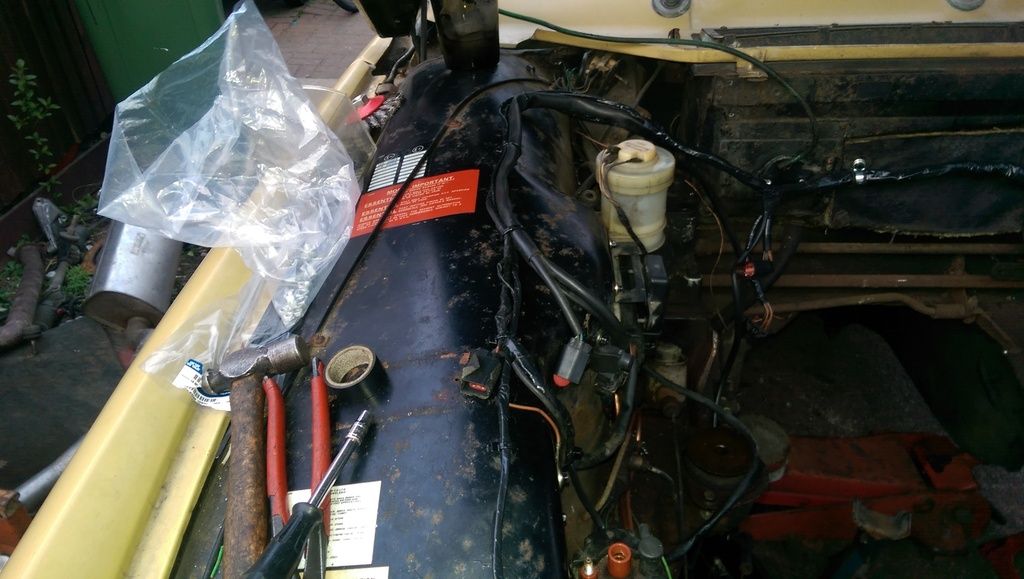
I am very pleased with how it has turned out.
Does anyone know where the ballast resistor is hidden? I am wondering if it contained within the loom somewhere and I would like to remove it as the Ford coil needs 12 volts.
Dan.
danm said:Does anyone know where the ballast resistor is hidden? I am wondering if it contained within the loom somewhere
Indeed it is.
danm
Member
Cheers mate,harveyp6 said:danm said:Does anyone know where the ballast resistor is hidden? I am wondering if it contained within the loom somewhere
Indeed it is.
Under the bonnet or behind the dash?
Dan