Info. required with 2000TC Throttle

Rocky Ward

New Member
Hi, I am restoring my 2000TC.

I bought an abandoned and annoyingly incompete project, yes I know I was asking for trouble :)

The engine was seized and I have it running nicely now, thanks to some new lids and stay up ethanol safe floats from Burlen (aka SU).

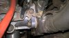
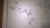
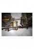
My next challenge is the throttle, its a tricky issue as I don't have ANY part of it.

I have fitted an old universal throttle cable to the rear HS8, which is enough to start the car while fiddling on the engine.

I have scoured the net for days and I have a Haynes Manual but the photos etc are just not clear enough for me to work out what I need.

The carb end has a pin which I have attached the clevis clamp from the throttle cable to, the diagrams shows an array of rods etc but none show the last inch to the carb.

Can anyone take some good close up photos of a stock setup or posts some diagrams etc so I can better understand what I need / don't have.

Many thanks, Karl.
 
Last edited:
Hi Karl,

The throttle on the 2000TCs doesn't use a cable. It's a series of rods and bell cranks. There is a rod that comes out of the bulkhead by the transmission tunnel, this is connected directly to the accelerator pedal. From that there's a ball and socket joint to a threaded push rod that goes to the throttle shaft that runs to the carbs. Which in turn goes to a lever that has a roller that runs in a slot for a quadrant on the actual butterfly shafts of the carbs. Rather long winded to say the least!

Unfortunately I'm at work but if need be I can Take a pic of the relevant page of the manual or parts book this evening.

As a matter of interest where are you based?

Best,

Steven
 
Steven,

Thanks for taking the time to reply, I am confused as the carb throttle assembly has a pin for a throttle cable with a clevis connection, which I have fitted.

I can see the page in the manual with the rods etc but can't see how this connects to what I have on the carb.

Assuming of course they are the original carbs - now I am beginning to doubt this.

I am in Burton, in the UK.

I have added a photo, so you can see what I have, as you can see on the RHS is the black throttle cable and split pin.

The pin is removable, leaving a small round hole.

The more I look at this photo, the more I think this small piece has been added, the big nut holding it on looks out of place and the small metal plate it is holding in place looks slightly different material / finish to it's neighbour.

Regards, Karl.
 

Attachments

  • WP_20170222_16_26_56_Pro SMALL.jpg
    WP_20170222_16_26_56_Pro SMALL.jpg
    298.6 KB · Views: 35
Last edited:
That
Steven,
The more I look at this photo, the more I think this small piece has been added
That looks like a later modification. The throttle is via a rod which runs between bulkhead and rear carb. But so long as it can be made to work then all is well.
 
Hi Karl,

Yep, that's someone's modification. They certainly didn't leave the factory like that :). I would offer a spare set I have. But its for LHD cars and I think there's some differences that might make things worse for you.

S-
 
Do you have a photo of what it should look like Rob ?
I am away from home at the moment but will be back at weekend. Actually my car has a 2200sc engine fitted but I've still got the old engine + carbs. I can take some pics on Saturday if that's not too late for you.
 
What year is the car? Can you take a picture of what linkage remains between the two carbs? And a shot of the steering relay in the car? Then we can figure out what's missing.

Yours
Vern
 
What year is the car? Can you take a picture of what linkage remains between the two carbs? And a shot of the steering relay in the car? Then we can figure out what's missing.
Its a late 1972. I will gladly take pics when I get home on Saturday, but bear in mind the engine/carbs I've got are removed from the car.

I can imagine your problem as I had some bits missing when I fitted the SC engine to my car - its not entirely obvious from the parts diagram how it all goes together.

Cheers
Rob
 
I have NOTHING in the car for the throttle.

I realise that there should be some bracketry on the steering idler, I have none of it.

I have no pedal and nothing inbetween the carb and the hole on the floor where the pedal should be :)

Thanks guys.

Regards, Karl.
 
If I remove this non-standard plate, will what I am left with connect to the rod/linkage do you think ?

I have attached a section of the Haynes Manual for a 2000 TC throttle assembly.

Obviously all the rods etc are inside the car, I presume all that is in the engine bay is Number 18, the Accelerator Coupling Shaft Assembly poking through the bulkhead.

I just can't see how this rod with its split pin will connect to my carb throttle, as per the initial photo above.

More puzzling is that surely the rod is an axial rotational movement and yet the current set up is vertical linear movement, so presumable all of this fitting is wrong not just the arm on the RHS with the clevis pin.

If I took it all off I would be left with a shaft that rotates but what part is missing to connect it to ?

The more I think about it the worse it gets, looking at this diagram it will rotate in the wrong direction too.

I desperately need a photo from you guys, showing me what it should look like.

Help !

Regards, Karl.
 

Attachments

  • WP_20170223_13_08_15_Pro SMALL.jpg
    WP_20170223_13_08_15_Pro SMALL.jpg
    215.8 KB · Views: 17
Last edited:
Hi, I converted to HIF6's years ago, but i found some photos of a previous rebuilt of the HS8s.
Have a look at the attached photos (they are thumbnails) and with the aid of the description in the previous posts, try to understand how it all works. If it is still not clear you can always ask again, but judging from what you say that you don't have, you really need a complete set-up out of a donor car.


DSC00844.JPG DSC00843.JPG DSC00845.JPG
 
I just can't see how this rod with its split pin will connect to my carb throttle, as per the initial photo above.

More puzzling is that surely the rod is an axial rotational movement and yet the current set up is vertical linear movement, so presumable all of this fitting is wrong not just the arm on the RHS with the clevis pin.

If I took it all off I would be left with a shaft that rotates but what part is missing to connect it to ?

The more I think about it the worse it gets, looking at this diagram it will rotate in the wrong direction too.
From memory ...
Attached to the carb is a nylon coupling which connects to that rod via the small split pin, this coupling functions as a simple universal joint.
The other end of the rod pivots in a bush on the plate fastened to steering relay, and that same end is a crank which points horizontally away from the engine.
The accelerator pedal twists a longer rod running horizontally across the bulkhead. This has a crank at the end, pointing towards the radiator.
There is a vertical link between these two cranks, as you push the pedal down this link gets pushed upwards and rotates the carburettor shaft clockwise as looking towards the radiator.

I know it's hard without a pic, but the same basic linkage layout is used in old series 2a land rovers as well as lots of other old (30's and 40's) cars. It would not surprise me if the P4 and P5 rovers were similar.
 
Demetris, thanks for the photos, the last one shows the rod I am interested in but frustratingly the end I am trying to find out about is hidden in the photo.

It does however not seem to be anywhere near the part of the carb I have the clevis in and throttle cable connected to.

I am now more confused than before.

I just need someone to take a photo of the end of this rod.

:)
 
Thats superb !

Thank you so much.

Now it makes sense it doesn't attach to the bell crank thing at all.

eBay here I come :)
 
Thank you to everyone who helped and took the time to reply to my query.

I am on the hunt now for this long shaft, I am hoping its an HS8 part not a P6 part.

Does anyone have one ?

Regards, Karl.
 
The attached image shows the parts I need, outlined in red. The numbers are from the Haynes Manual Exploded Diagrams.
  • 97 - Countershaft & Lever
  • 98 - Coupling
  • 101 - Plain Washer
  • 102 - Circlip
  • 62 - Throttle Lever
  • 63 - Nut 10 UNF
  • 99 - Roller
  • 100 - Circlip
  • 18 - Accelerator Coupling Shaft Assembly
  • 21 - Tubular Pin
  • 22 - Split Pin
Regards, Karl.
 

Attachments

  • THROTTLE BITS I NEED.jpg
    THROTTLE BITS I NEED.jpg
    55.4 KB · Views: 11
Last edited:
Back
Top