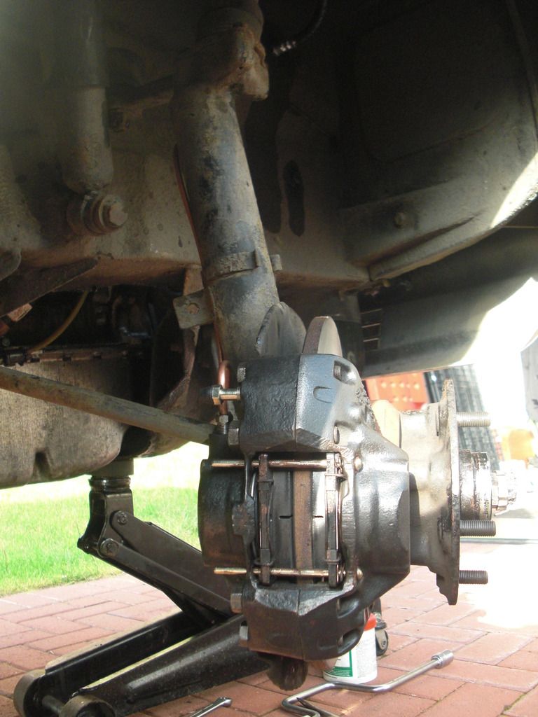
I've had quite a bus weekend lying underneath the good Lady sorting various jobs and giving her a major service. For me, a major service gets done every 10,000 miles, which I cover in roughly 7 or 8 months. As well as all the usual service items I wanted to replace the diff front pinion oil seal. The diff has always leaked from the front so it's a job I've been meaning to tackle for ages :roll: . No pictures I'm afraid, but suffice to say that it was fairly straightforward. Disconnect prop shaft from diff, remove drive flange bolt and drift off the flange, dodging the oil running out the front of the diff. Prise old seal out with screwdriver, fit new seal and flange, torque to 35 lb ft, refit prop shaft, fill diff with oil. Easy peasy he says

. Still took me 3 hours to do all that. Hopefully there will be no further leaks, fingers crossed.
As part of the service I also wanted to check the condition of the main bearings. It's been nearly 20,000 miles since I last had a look at them and with the recommendation to replace them at 50,000 miles (Lady C has now done 84,500 miles) I want to make sure they don't wear too much before I get a chance to replace them. Obviously I'm simply removing a bearing cap and looking at the bearing in that, so I don't know what sort of condition the bearing on top of the crank is in. I could have slid a couple of the easier ones to remove out, but then I might as well replace them if I'm going to that extent. You could probably argue that I might as well replace them all if I'm removing all the caps anyway, which is possible with the engine in situ, but I know that No 1 main is particularly tricky to remove due to the pressure on the crank from the lower timing chain so I chose not to at this stage.
So after another 20,000 miles how do they look? Surprisingly good I think. Here they are in order with comparison photos of No 2 and No 4 from the last check done at 64,000 miles.
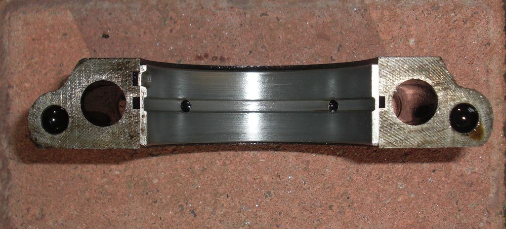
No 1, front
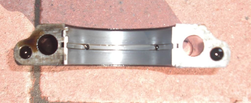
No 2
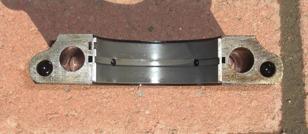
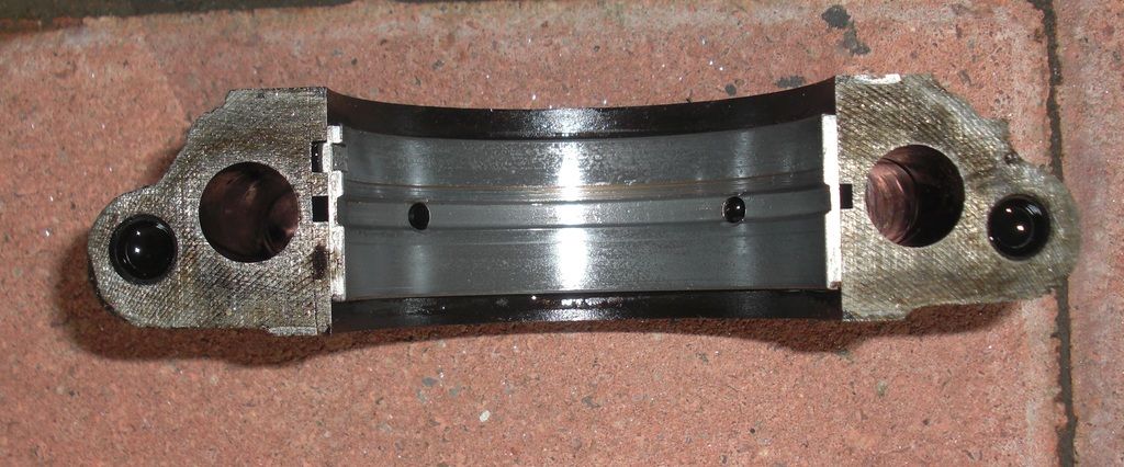
No 2 from 20,000 miles ago
No 3 (centre), this one is actually just starting to show some copper in the upper left quarter
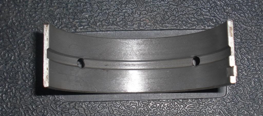
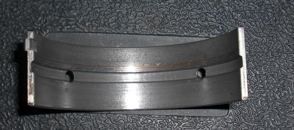
No 4, still with that groove
No 4 from 20,000 miles ago
No 5 , rearmost
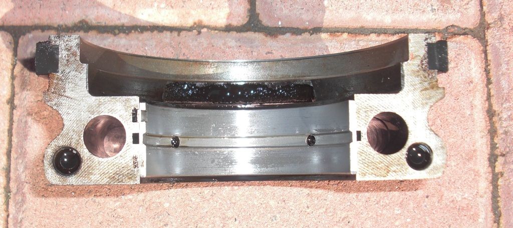
So perhaps showing a little bit more wear than previously, but still pretty good, and nowehere near as much as I'd expect from an 84,500 mile engine. I think this is probably due to the engine oil and filter change every 2,500 that I do, but perhaps I've just been lucky.
My plan now is to pull the engine out at 100,000 miles and replace all main and big end bearings. I've also got to replace the side plates and the rear crank seal too. Job for the summer next year then
Dave