Overhauling a knackered engine.

Gargo

Active Member
I've started overhauling a very worn engine and thought some of you may enjoy the process. I'll show the old tired stuff, but the focus will be on the new and improved.
Here goes:
The old cam is on the right,
resized_dsc03689.jpg


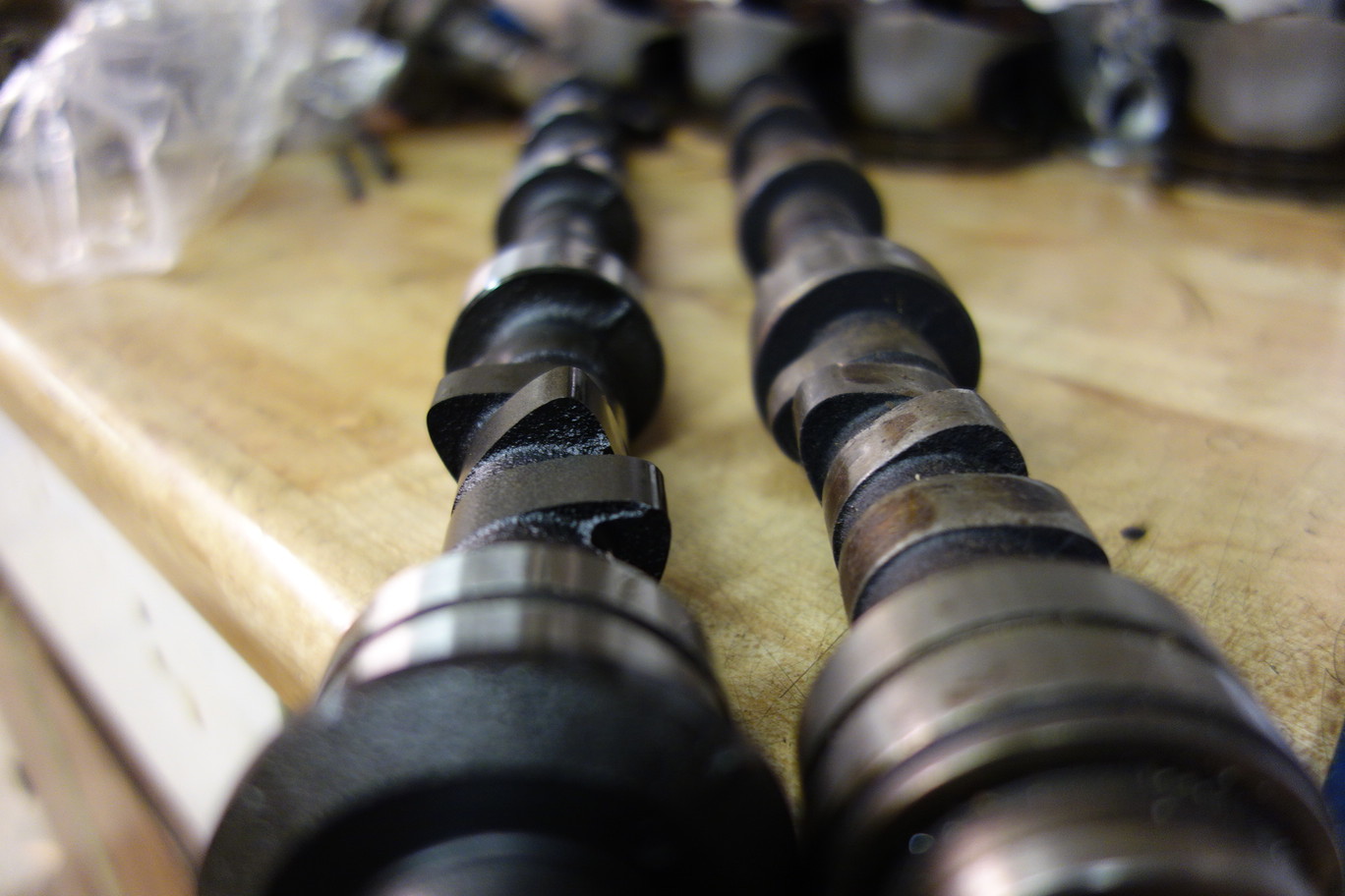
The old cams standard lift of 6.6mm has worn down to 3.8mm on two lobes, only one lobe is giving over 6.0mm of lift!!! It's no wonder why many suggest you renew a standard cam to improve the power of an old engine. The new cam shown here is a little bumper :D and will push these rockers,

resized_dsc03691.jpg


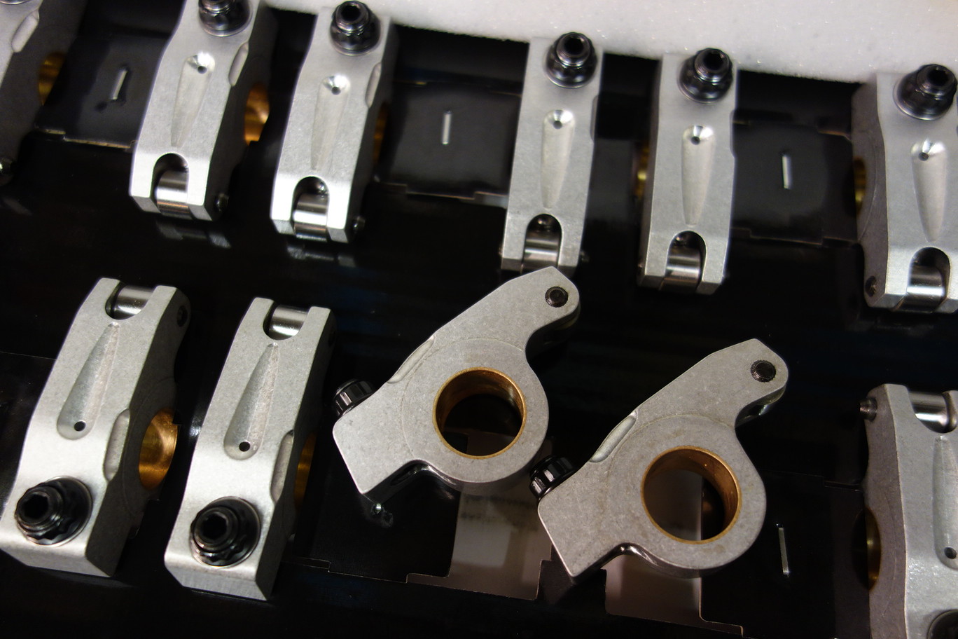
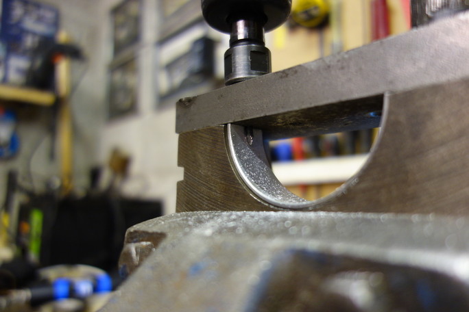
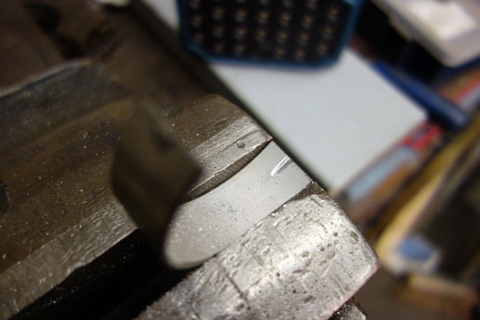
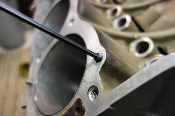
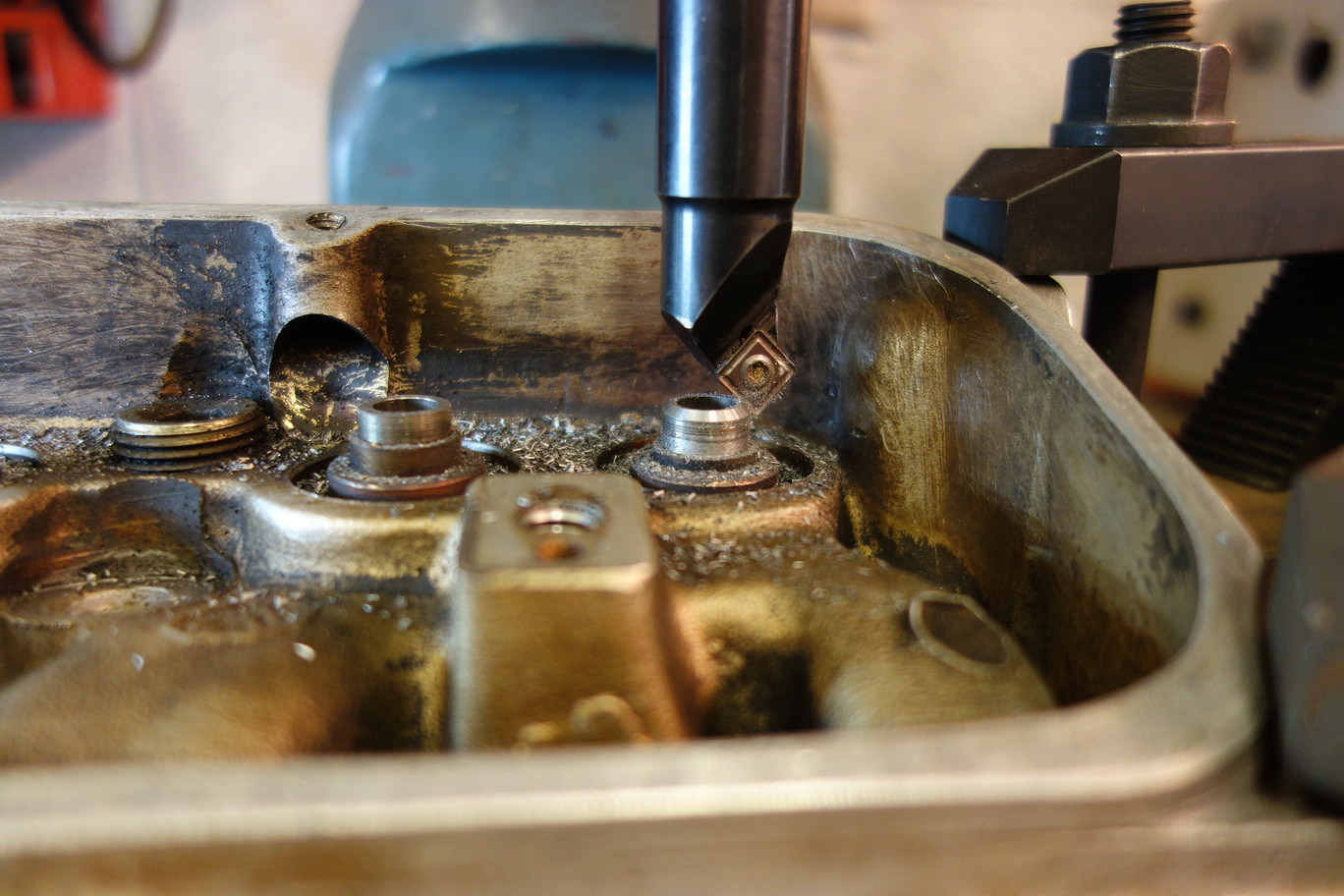
The problem of a bumper cam is that the valve guides are too high and the valve caps hit the valve seals, so you simply move the valve guide seal profile down the guide. Some may push the guides down into the head but this would restrict the gas flow in the ports, so machine the top off the guides.
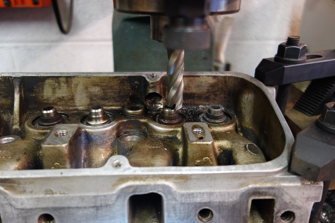
resized_dsc03687.jpg

and re profile
resized_dsc03688.jpg
 
Wow, this looks like its going to be a very interesting rebuild to follow. I am also keen on these rocker and would like to know more about them.
Regards, Barten
 
Cafcpete - Bang on the money, you even got the supplier; where do I send your prize, the old knackered rockers :p

How are they to fit, a penny for your thoughts?

Graeme, Terra Yella are from your part of the world, I think.

The blurb says: a lighter and stronger valve train, reduced friction and less radial loading on the valve guide. More power and less maintenance. They'll give adjustment for the preload, no shimming the rocker pedestals, thus avoiding a less than ideal rocker geometry.

The build is nothing radical, but hopefully just done correctly, although up until last week I was limiting the cam lift to fit standard valve guides; now that has gone out the window.....
 
Haha, thought so :)

I went with these for similar reasons, I was fitting a higher lift cam and didn't want to shim the rockers. Before I spoke with Paul at V8tuner I was going to fit adjustable rods but he convinced me to splash out on the yella terra as I would have needed new std rockers anyway.

To my shame I have to say I didn't fit them.......... I had the engine assembled by Colin Gould who is doing the restoration of my car. When I spoke with him about the rockers, he said they weren't a problem to fit once he had read the instructions! So I don't think you will have any issues.

Good luck with e build.

Peter
 
I think we need to look at cams and timing gear on the RV8 as effectively service items rather like people change cam belts on other engines. "knackered" to me means re-bore or new bearings. A cared for RV8 should be well into its 3rd or 4th cam by this time!

Which cam did you go for in the end?

I'm 50:50 on fitting the valve seals at all. I understand the later guides are a slightly different material and that the decreased lubrication on earlier guides can lead to accelerated wear. Personally as the oil only lives 3000 miles anyway, then I'm prepared to live with less effective oil/gas control. Did you fit new valves and guides? A complete kit including the better 4.6 waisted stem valves is only £120.

I notice you have later EFi heads, I see no reason why anyone should keep the P6 originals, there is just no downside to this upgrade.
 
I think you're right on the cam being consumable.

I have fitted the 229 cam to a 3.9 for a bit more bottom end torque, with the waisted guides and valves. The block has been +20 bored and balanced.

I'm looking forward to seeing what output I'm getting when the car goes to the rolling road for tuning:)
 
I'd be expecting 200 bhp ish at the flywheel. You'll lose out to later cars at the same spec engine as the manifolds and exhaust are restrictive on the P6 maybe costing you 10-15bhp.

That'd be 175 with a manual box at the road 150 with an auto. Going to be quite rapid as you are 300kg or so lighter than something like an Audi A4 with this kind of output.

Don't forget to post your dyno graphs!
 
I used Yella Terra rockers too but had a hell of a job getting the split pins in the holes, when assembled as per the instructions the end 4 rockers were really really stiff - a weight of between 300 and 700grams was enough to turn the "middle" (depending on how wound up the rocker shaft springs were) rockers but the ends took 1200 to 1400 grams!
I ended up making thin spacers to replace the curved washer, did anyone else have a similar problem?
They weren't part of my rebuild plan until I found they were actually a lot cheaper than genuine rockers (I was very dubious about aftermarket rockers after hearing various stories of the very poor quality copies out there)
 
After a rebore the block was cleaned to what looks like spotless, however a few magnets placed into voids will grab the little filings that will kill an engine.
resized_resized_dsc03698.jpg

I should have really put the magnets into a plastic bag to keep the filings off the magnet.
resized_resized_dsc03699.jpg


I'm not going to write about how to build an engine but just concentrate on the modifications I've made along the way. All the mods are from the D.Hammill book, How to Power Tune the Rover V8


As described in the book maintaining the oil pressure from the front to rear of the engine can be helped by closing down the oil feeds to the cam shaft, so I drilled smaller oil feed holes.
resized_resized_dsc03732.jpg

resized_resized_dsc03733.jpg

Which must be inserted with care to align with the oil way feed holes.
 
Next was modifying the main bearing to allow the pressured oil to feed the big ends for a longer period. So the oil grove the main bearing uppers are extended into the lowers.
I setup a jig to try and achieve this.

resized_resized_dsc03737.jpg


but the result was not to my liking so I finished them off by hand with the die grinder.
resized_resized_dsc03738.jpg


Resulting in an extended oil grove.
resized_resized_dsc03739.jpg


And also the oil feed to the rockers can be restricted by drilling a grub screw

resized_resized_dsc03741.jpg


and placing into the block's head oil feed.

resized_resized_dsc03742.jpg
 
Next I tried to fit the new pistons to the conrods, but my home made tool was not up to the job and the pin caught on the piston wrecking the piston's gudgeon pin hole.
resized_resized_dsc03750.jpg

So it was put on the piston collection shelf. Bottom to top, Rover 4.6 V8, Cosworth 3.0 DFV, Rover 1.4, BSA .25 c/w std allow conrod
resized_resized_dsc03755.jpg


The guys at Real Steel provided me with a replacement piston and fitted the full set to the rods.
 
So I assembled the heads with new valves.
resized_dsc03759.jpg

and made the cam bolt to be a thrust bolt, with a nylon insert. Making and getting the cam end float to be just right was nearly a days work, it's no wonder my girl friend looks at me sideways when I say I've spent all day fitting one bolt.
resized_dsc03763.jpg

And holding the cam on (note in this picture the spacer is the wrong way round). I only corrected this after review my photos once I'd assembled the timing cover and water pump.
resized_dsc03760.jpg

So on went the heads and those lovely rockers.
But even though the supplier of the uprated push rods told me that I may need to open up the push rod holes in the heads, I didn't as I thought he meant that the rods are too big to pass thought the holes. At this point I found out what I was being warned about, it is the geometry of the rods in the holes is the problem. I could see that the rods were interfering with the head.
resized_dsc03797.jpg

But I've torqued up the heads and assembled the valley etc, what the earth am I to do?
 
I removed the rockers and taped up the whole of the valley and the heads, to drilled the holes.
resized_dsc03804.jpg


So I now have a complete engine.

resized_dsc03812.jpg
 
The next problem was after removing the engine from the engine stand I found I had not tested the P6 flywheel up to the crank. There was a locating dowel in the end of the crank. I reached for the tank tape again and taped the dowel through.
resized_dsc03868.jpg


and screwed a bolt into the threaded dowel to push the dowel from crank.

resized_dsc03869.jpg


Next I could not persuade the crank oil seal in. I didn't have access to the proper tool. After a long time trying I ended up making a little pressing tool that worked very well.

resized_dsc03871.jpg


There is another days work and very little to show, but a big step forward.
 
Next I turned to the inlet manifold. Matching the ports to the heads, which is very very difficult as the opposing head faces are at odd angles. It is straight forward to match the vertical faces, but I could just not think of a good way to match the the floor and ceiling of the ports. I could find nothing online or in any of my books. The problem is you can't see in to the manifold to check the heights.
The same sort of problem existed for fitting the valley gasket, because the heads are on thinner head gaskets the ports are lower down the valley. The distance between the inlet port in the valley gasket are now too far apart, but how far down do you cut the gasket ports? This is added to because the inlet manifold mounting bolts are not a 90 degrees to the face, but pull the manifold down into the valley, how do you get all this to line up? So I continued....
The two middle inlet ports in the manifold being matched to the gasket.
resized_dsc03854.jpg


And the SU mount ports have a sharp turn down into the manifold
resized_dsc03866.jpg


These were blended into as large a radius I could get
resized_dsc03865.jpg
 
Now the engine is complete, I filled the engine with oil and turned the oil pump
resized_dsc03879.jpg


and was happy to see the oil seeping out where it should.
resized_dsc03878.jpg


and once turning the engine over again the cam lift is appearing at the rockers. Lift lovely lift....
resized_dsc03882.jpg


And the completed engine waiting to be lifted into the P6.....
resized_dsc03887.jpg
 
I looked at port matching. The general advice in the RV8 world I've concluded from reading far too much is don't. Any gains are only really to be had around the valve area. That and some general cleaning up of the casting.
 
I assume you mean don't spend to much time trying to acheive the impossible and then worry it's not right, rather than a firm "don't attempt it". I realise I've not posted pictures of the work around the valves, but it has been done.

As per the tuning book, I've put a separation plate into the standard air box and the only external visible clue to the state of the engine will be the larger inlet. I felt I had to make it bigger due to the separation plate splitting the inlet in two.
resized_img_20170718_105001-e1501412990365.jpg


Widened to double the area.
resized_img_20170718_105124-e1501412935742.jpg


When adding the material I add forgotten that the inlet passes between the carbs, some times things just workout fine....
resized_img_20170718_174053-e1501413029656.jpg
 
Last edited:
Back
Top