Rover P6 BW65 gear shifter set up

roverp5Bcoupe

Active Member
I am fitting a ZF4 HP22 to my Rover P5B and am now looking how to arrange the gear shifter.
The P5B has rods between the shifter and the BW35. I read that the BW65 in a P6 uses a cable between box and shifter and that this would be a good set up for the ZF4HP22 conversion.
Does anybody have a picture or a drawing from the parts manual which shows the shifter, cable and the connection to the autobox?

Thanks in advance

Peter
 
In the P6 both the BW35 and BW65 use cables and you need a slightly modified Jaguar cable (I believe). If you talk to Andy Morgan (eightofthem) he will be able to help you. I got my ZF from him with this already installed.
 
In the P6 both the BW35 and BW65 use cables and you need a slightly modified Jaguar cable (I believe). If you talk to Andy Morgan (eightofthem) he will be able to help you. I got my ZF from him with this already installed.

Peter, i got my box also from Andy with this Jaguar cable but i am wondering what the best cable routing would be: routing the cable from the gear lever to the front or to the rear of the car.
How are you routing your kick down cable? You have to be carefull because the stroke of the KD cable on the BW35 box is aproxx 10mm longer than on the ZF4 box so i modified the linkage arm

Peter
 
35 is a rod linkage, 65 is a cable. The cable set up isn't the real problem, the difficulty is getting a seven position selector gate.

Harvey,

You are right. That will be a challenge but do-able i believe. I have an original LDV shifter so it should be possible to more or less copy the pattern on the P5B shifter

Peter

Thanks for that drawing. I already found that. Do you happen to have a drawing where the bracket fitted to the tunnel which holds the cable is visible

Peter
 
Peter, i got my box also from Andy with this Jaguar cable but i am wondering what the best cable routing would be: routing the cable from the gear lever to the front or to the rear of the car.
How are you routing your kick down cable? You have to be carefull because the stroke of the KD cable on the BW35 box is aproxx 10mm longer than on the ZF4 box so i modified the linkage arm

Peter

That's an issue I've yet to tackle. Andy sent my a used selector cable with a modified mounting bracket and "the correct" selector arm (Jaguar), which apparently makes it simple(r) to find all 7. I quote his email below:

The adjustment for all positions will be a lot easier with this cable, just make sure the actual selector arm points upwards, rather than downwards as it is now. ( use the arm on the replacement cable )
Warrens issue was with the selector arm, he had the type you have fitted now, and it will not work with that cable without modification, if he had the jag arm as well it would have made it easier.
Just bear in mind the bracket position in the tunnel for the cable to fit too, make sure the selector arm is all the way forward ( box in park ) and the inner cable as far out as it needs to be, before deciding where to fit the bracket, this should give you enough adjustment to obtain all positions

Hope this helps. Really nothing is too much trouble for Andy. The most helpful transmission specialist I've ever dealt with!

Peter


Peter,

Andy is a really helpful person but he must have run out of second hand selector cables. Can you post a picture of this cable and the bracket. Reading Andy's e-mail, i draw the conclusion that the shifter cable runs towards the front of the car. I believe there has to be changed something in the shifter to get all 7 positions. I guess that the selector arm you received is shorter and leads to a shorter stroke of the selector cable which can be handled by the P5B/P6b shifter.

Here is a picture of my KD bracket which may be different as yours

Before modification
CIMG4026.jpg


Modified
CIMG4028.jpg


Peter
 
Andy originally supplied a brand new cable and the 2nd hand one came later, so I'm guessing it's a question of what he has available to him at the time and he took pity on me. I guess I was lucky in this case. I'll post a pic later if this is helpful. I see you also have nice, metal bushes and couplings holding everything together for the throttle linkages. My nylon ones disintegrated at exactly the wrong time so I too have something similar. Frankly these components were utter crap, at least on a P6...

Your control cable solution looks really neat and easy to adjust.. I'll by keeping a copy of that picture. What is the distance between the pivot centres of the arm you made for reference?

I think the sticky thread needs an update on how to sort these details. They aren't so difficult but they could take a lot of time and frustration, especially as in my case the lack of a garage means I'm paying someone to do this.
 
The dimension from center pin to center pivot arm is 38mm.
The metal bush i made from a part from a Rover steering fluid reservoir. I cutted both end off and drilled the hole up to the right diameter
DSCF4425.jpg


Peter
 
image.png
Peter,

Andy is a really helpful person but he must have run out of second hand selector cables. Can you post a picture of this cable and the bracket. Reading Andy's e-mail, i draw the conclusion that the shifter cable runs towards the front of the car. I believe there has to be changed something in the shifter to get all 7 positions. I guess that the selector arm you received is shorter and leads to a shorter stroke of the selector cable which can be handled by the P5B/P6b shifter.

Peter, the cable route points to the rear of the car from the shifter, and loops forward to the selector arm on the box, just as the picture above suggests.

The actual selector inside the car will not need to be modified if the cable and brackets are all set correctly, you will just be able to select position 1 at the bottom of the gate, all the others just about fall in to place at the same point as the old 35.
I still have the jig set up that I used when working with Warren on his, if you get into trouble let me know.
 
Looking at this picture Peter, it appears the inner cable is a little too tight, with that much cable pulled out I think the throttle valve / cam is already open.
If you release the clevis pin and allow the inner cable to return, you should then be able to gently pull the inner cable outwards and feel the slack come up until you feel a little resistance, that should be your start point for adjustment, and you will need to adjust the outer cable upwards to enable you to refit the clevis pin to the arm.
image.jpeg
 
Looking at this picture Peter, it appears the inner cable is a little too tight, with that much cable pulled out I think the throttle valve / cam is already open.
If you release the clevis pin and allow the inner cable to return, you should then be able to gently pull the inner cable outwards and feel the slack come up until you feel a little resistance, that should be your start point for adjustment, and you will need to adjust the outer cable upwards to enable you to refit the clevis pin to the arm.
View attachment 9780

I will check if the cable is too tight. Am i right suggesting that the stroke of the KD cable on the BW35 is approx 25% larger than the stroke of the KD cable on the ZF box?

Peter
 
View attachment 9779

Peter, the cable route points to the rear of the car from the shifter, and loops forward to the selector arm on the box, just as the picture above suggests.

The actual selector inside the car will not need to be modified if the cable and brackets are all set correctly, you will just be able to select position 1 at the bottom of the gate, all the others just about fall in to place at the same point as the old 35.
I still have the jig set up that I used when working with Warren on his, if you get into trouble let me know.


Andy,

In the e-mail to Peter ZRH, you say that the actual selector arm should point upwards. I believe that the selector can only work well when the cable points to the front of the car.
I had seen the drawing you posted and had a look at the P5B tunnel and if you run the cable from the shifter to the rear of the car, then the cable adjustment nuts will be underneath the not removable part of the tunnel so adjustment of the cable will be very difficult and can only be done from underneath and the adjustment nuts will be above the propshaft and cannot be reached easy.
The jaguar cable you send me doesn't have two adjustment pieces like the P6B cable has
If the cable go's from the shifter to the front of the car, you can make an extra inspection cover and after removing this extra cover, adjust the cable with the shifter installed.
Do you have a picture of the cable bracket near the shifter?

Peter

Peter, the Jaguar cable with the Jaguar selector arm fitted needs to point upwards.
The Rover selector arm points downwards, they are totally different.
If you can get your hands on the 65 cable then by all means use that one, the bracket on the tunnel can be made to suit your needs, it is fairly straightforward when you have it all in position, you have the benefit of the tunnel cover that can be removed for access , the P6 boys don't have it that easy.

You can always modify the selector arm end of the cable with a clevis fork instead of the ball joint. The end is threaded for slight adjustment.
 
Hello Andy,

I checked the KD cable but is was adjusted ok

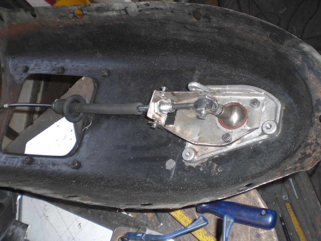
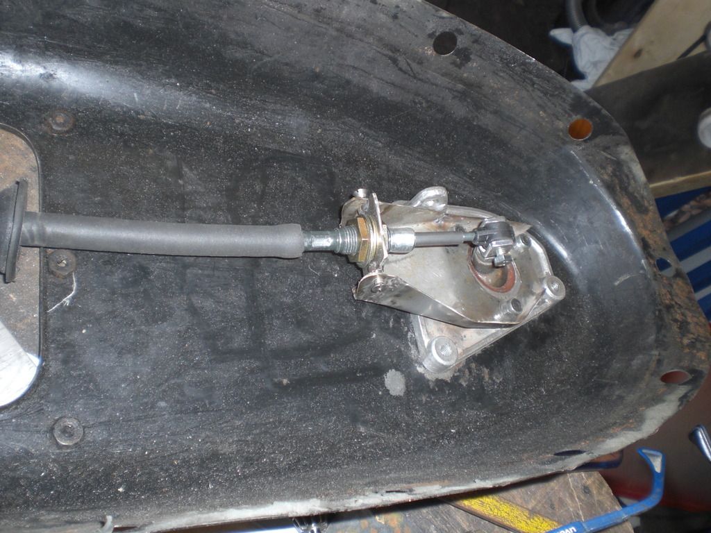
Thanks for the reply. In the mean time i got a little further. A shifter bracket was made for the cable which is fitted onto the shifter.

CIMG4047.jpg


CIMG4048.jpg


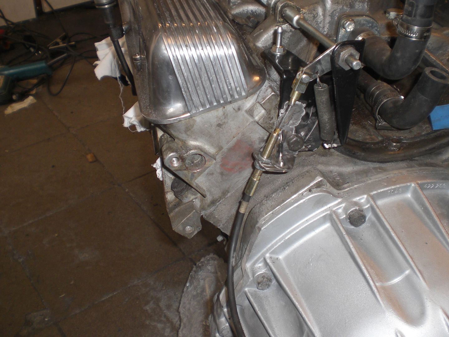
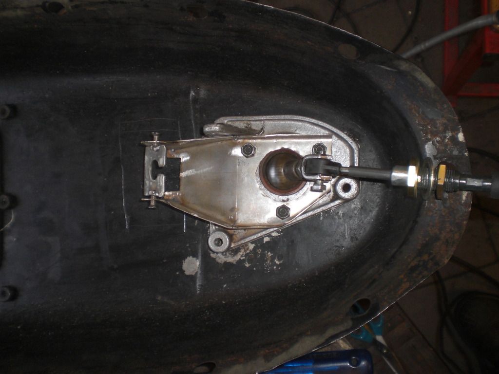
I choose to run the cable towards the front of the car because if i would let it run to the rear of the car, the bracket would be in an awkward position as you can see in the picture underneath.
The adjustment items would just be underneath one of the cover mounting bolts.

CIMG4049.jpg


Some remarks:
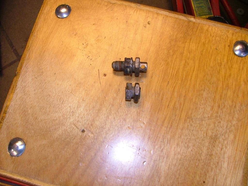
1- the cable connection to the bracket is made so that it can rotate. The cable end is a metal rod which cannot follow the circle movement of the shifter end if the bracket cannot rotate. I saw that a the movement of this cable end on a Jaguar shifter makes a straight movement and not a circle movement like the rover shifter.
2- another inspection hole will be cut into the cover so the cable can be adjusted with the shifter and cover installed.

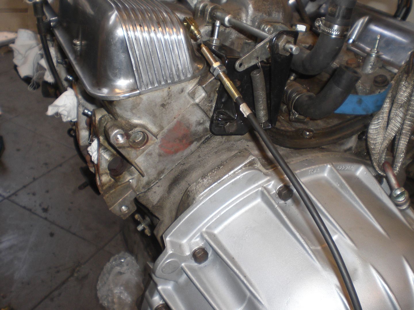
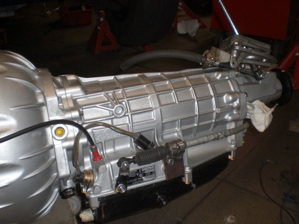
Here's a picture of the connection to the box

CIMG4052.jpg


A second hole has to made in the bracket and the shifter bracket will be modified to a clevis type bracket as was done on the shifter side..

You mention that the bracket has to be moved upwards. This is true if the cable runs from the shifter to the front of the car. If the cable runs to the rear of the car, i believe the shifter bracket on the the box has to point down (it was fitted like that when i received the box)


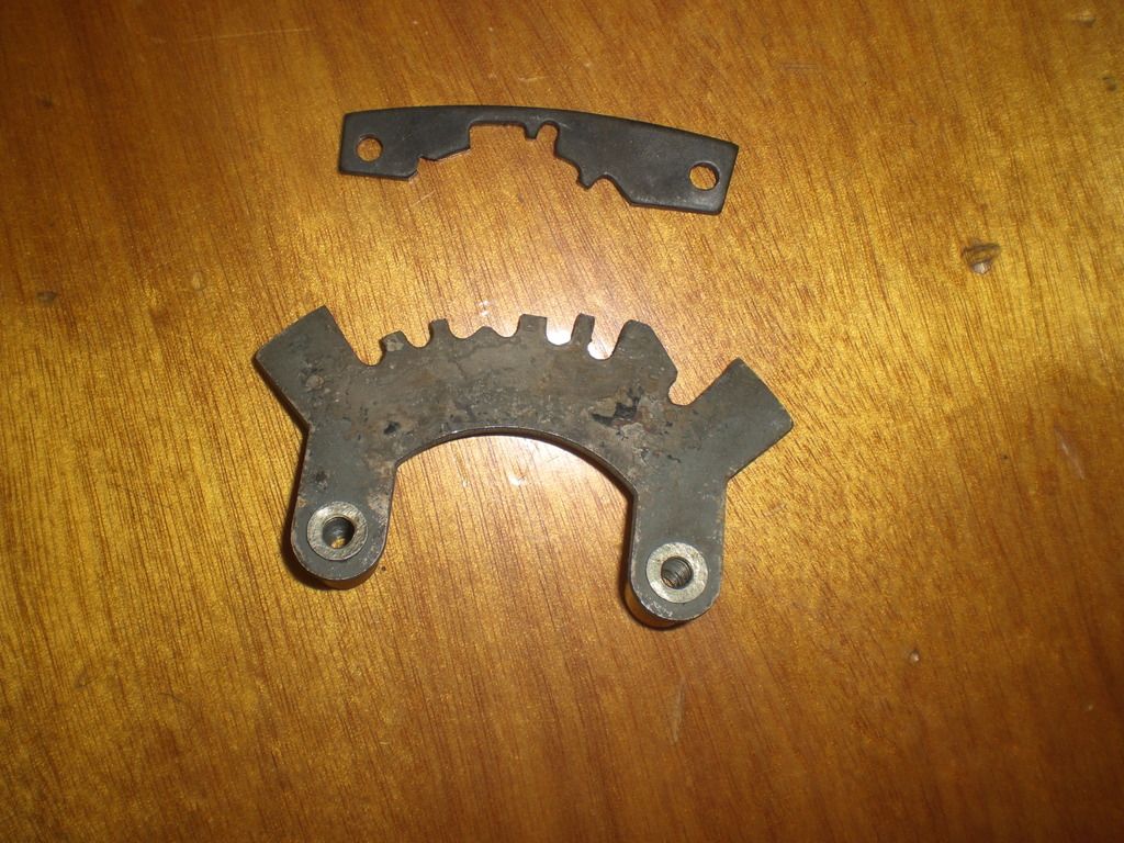
Underneath a picture of the shifter locking patterns (top = Rover/BW35, down = LDV/ZF4). With the current set up, all 7 positions can be reached but the lockup pattern is not 100% so if you could send me the jig you made, i would be very happy.
CIMG4053.jpg


Thanks again for your help.
Regards

Peter
 
Back
Top