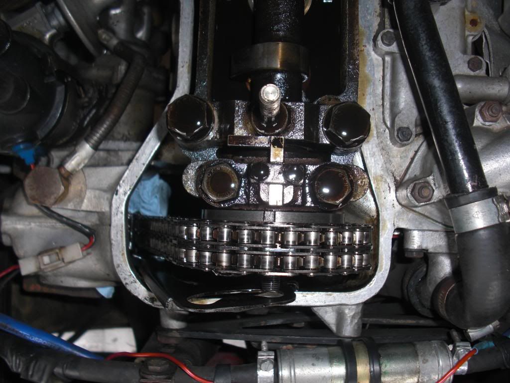
Right, I've attached a few exploded diagrams to show where everything is. (It's deliberately massive so you can download it

)
Diagram key:
* - Securing nut for use when mounting it to the 'smiley face' support bracket. You will need to obtain one of these - one of the nuts on the steering idler bracket behind the carbs will do ideally in the short term
A - 'Smiley Face' Steel support bracket
B - Vernier set bolts
C - Lock-tab
D - Circlip. Sits into the first groove of the chainwheel (F)
E - Vernier assembly. Teeth on the rear side engage with inner groove of chainwheel.
F - Chain wheel
G - Chain tensioner adjustment access hatch.
H - 4mm Allen key and small 7/16 AF socket needed to back off chain adjuster.
I - Round inspection hatch. Useful for slotting in a thin piece of wood to prevent chain tensioner pad springing out into the sump when working on the chain wheel above. Take care prising the alloy cover out - it will chip! Use two blunt screw drivers with cloths around them to lever it out.
J - 'Smily face' steel support bracket
K - Vernier assembly and chain wheel complete.
L - Camshaft
M - Camshaft flange. Set bolts (B) bolt into this flange through chainwheel.
N - Chainwheel (F)
O - Vernier assembly complete (E)
P - 'Smily face' steel support bracket (A)
Q - Securing nut (*)
Aside from the chain tensioner inspection hatches, you only need to remove the rocker cover (3x 1/2 AF bolts) to gain access.
As mentioned elsewhere, the trick is to back off the set bolts until they are just held in by one or two turns (as shown in the bottom diagram). Pull the vernier assembly (E) forwards and tie it to the steel support bracket with the securing nut. Then push the chainwheel backwards over the camshaft flange (M) (Gap between O & N in picture is bigger than reality). Provided the camshaft is locked in the correct position, all you need to do is place pressure on the left (non driven - rotation is clockwise) side of the chain (where the arrows are) to rotate the chainwheel as far as it will move. Then push the vernier back into the centre. The vernier teeth will start to grip. Screw the set bolts (B) in as far as they can go at this stage before removing the securing nut (Q/*). Keep the tension of the chain. Pull the chain wheel forwards into full engagement with the vernier, nip up the bolts, put the circlip back in and knock the tabs over. Provided the cam and crank are locked at the correct positions, and you put enough tension on the left side of the chain, it will line up fine.
Michael


