

Some engine manufacturers incorporate oil filter bypass valves within the oil pump front cover, while others don’t and in these cases the oil filter itself has a bypass valve built in.
The bypass valve whether it is within the oil pump cover or within the filter is there to prevent the filter, should it become blocked from suffering permanent damage, which could include bloating with possible rupture of the metal canister resulting in massive oil loss or rupture of the rubber seal at the front cover / filter interface. Both of these failures could result in the engine being ruined through bearings running dry etc.
I have been having a look at the oil pump front cover that was on my original 3.5 litre engine, a new cover of exactly the same type (P6B) was fitted to the 4.6 which now powers my Rover.
Oil is drawn up from the sump passing through a gallery within the block before entering the rear of the timing cover and into the oil pump gear chamber. Passing around the gears the oil is then forced under pressure through a rectangular slot located at the front of the oil pump front cover and into the spigot chamber where it meets the filter. Entering through the ring of small holes and pushing aside the rubber anti drain back valve and down through the filter media before returning via the central cylindrical chamber and into the spigot which retains the filter.
Travelling along a single gallery within the front cover, the oil will meet with two ports both on the output side before entering the timing cover again and thence into the engine for distribution. The first port (A) contains the oil pressure switch, which will activate the red instrument light should the pressure at this point fall to 8 to 10psi or less.
The second port (B) contains the oil pressure transmitter which records the pressure of the oil as it leaves the front cover and enters the engine, displaying such on the instrument gauge. The orientation of these two devices can be reversed with no ill effects.
The P6B oil pump front cover also incorporates two pressure relief devices.
(1) A filter bypass valve.
(2) An oil pressure relief valve.
The filter bypass valve located on the input side sits at the base of the spigot in the same plane as the first port. It consists of a spring loaded disk which is normally closed. Should the oil flow into the filter become impaired, either from cold oil or a possible blockage within the filter media, with the subsequent increase in oil pressure at this point exceeding the bypass valve spring pressure, then the valve will open allowing oil to flow unfiltered back into the engine. It does so via the aforementioned port (A).
The oil pressure relief valve is a safety device with the intent to limit maximum oil pressure to 55 or 60psi and is located also on the input side and in parallel with the filter bypass valve. Activation will occur usually from a combination of oil temperature and engine rpm, and when open will allow excess oil to short circuit the filter and the engine, essentially looping in a circle between the spigot chamber and the oil pump gears.
When the engine rpm drops for the given oil pressure, so the pressure relief valve will close. However should the valve remain open as the engine rpm drops, then oil pressure will fall as the volume of oil being moved per unit time will also fall. Oil will keep short circuiting the filter and the engine with pressure on the output side, measured as it would enter the engine falling essentially to zero. Unless the engine is switched off very quickly, permanent damage may result.
Since 1986 I have used a variety of oil filters on my P6B, including Unipart GFE 145, JRA branded RTC 3186, Coopers Z15A and Pennzoil PZ-2.
Other filters to name but two that I have not used that are suitable for the P6B are Fram PH25 and Wix 51069. All of these filters have anti drain back valves (the rubber flap beneath the ring of entry holes on the filter face) but none have inbuilt bypass valves.
A filter with an inbuilt pressure bypass valve by inspection will have either a small hole at the far end of the filter when looking into the large threaded centre hole and / or a coil spring visible at the far end within the same threaded hole.
Such a device is activated when the pressure gradient measured across the filter from point of entry to exit exceeds a pre set figure, usually 8 to 11psi in the case of filters designed to meet the requirements of later oil pump front covers for the Rover V8.
I cannot say if these include the SD1 but certainly Land and Range Rovers of all capacities from circa 1975 till 2004.
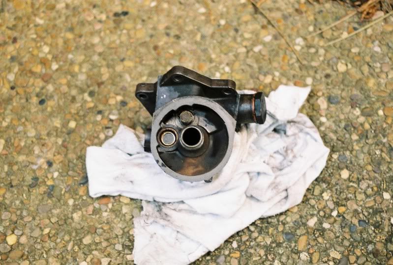
Oil pump front cover with spigot in the centre, bypass valve on the left and meshed entry to pressure relief valve above.
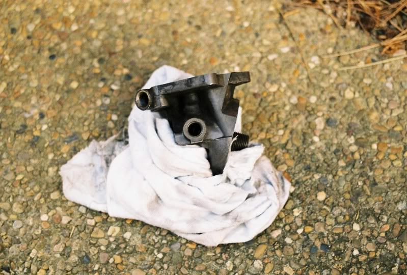
Ports A and B right to left.
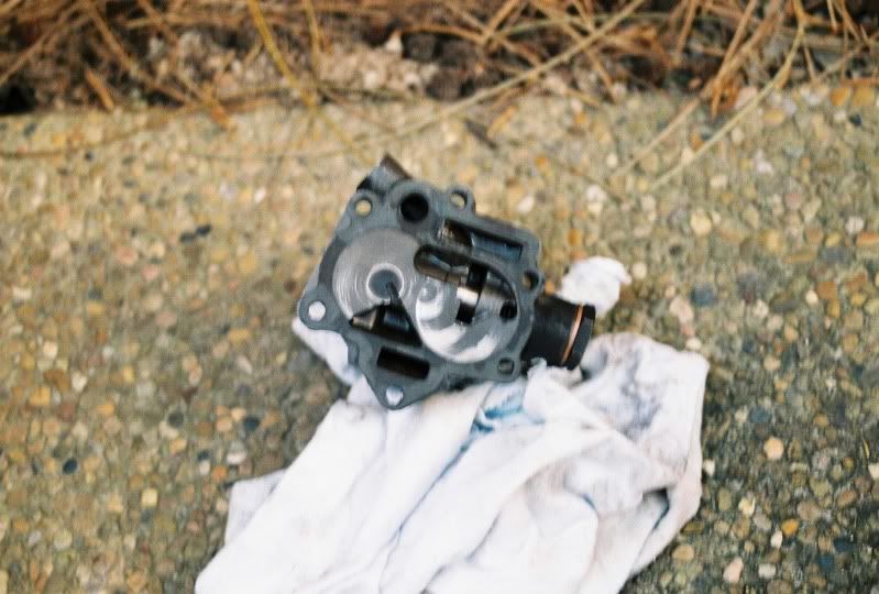
Cover base with pressure relief valve closed.
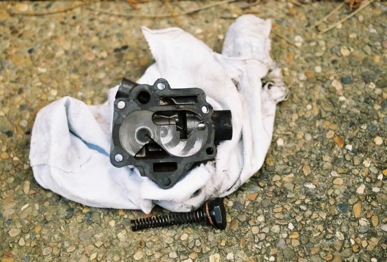
Pressure relief valve open with spring removed. The rectangular slot at the bottom is the entry point for oil into the spigot chamber, while the larger hole on the top left is the exit point for oil returning to the engine via the timing cover. The gears spin against the front cover, cushioned by a bed of oil residing in the cavities beneath them.
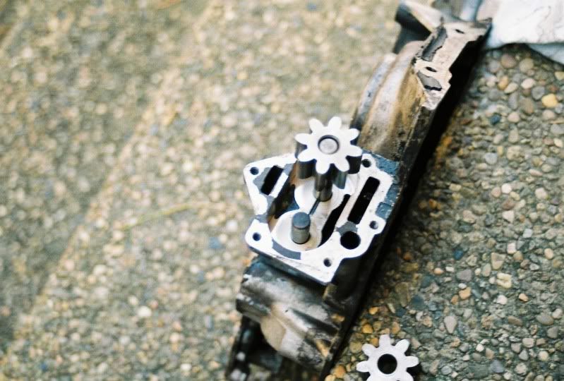
Timing cover with oil pump gears removed from gear chamber. Oil enters the gear chamber via the slot on the right at the base of the gear chamber and exits via the hole at the front then up through the rectangular slot and into the oil pump front cover.
Ron.
The bypass valve whether it is within the oil pump cover or within the filter is there to prevent the filter, should it become blocked from suffering permanent damage, which could include bloating with possible rupture of the metal canister resulting in massive oil loss or rupture of the rubber seal at the front cover / filter interface. Both of these failures could result in the engine being ruined through bearings running dry etc.
I have been having a look at the oil pump front cover that was on my original 3.5 litre engine, a new cover of exactly the same type (P6B) was fitted to the 4.6 which now powers my Rover.
Oil is drawn up from the sump passing through a gallery within the block before entering the rear of the timing cover and into the oil pump gear chamber. Passing around the gears the oil is then forced under pressure through a rectangular slot located at the front of the oil pump front cover and into the spigot chamber where it meets the filter. Entering through the ring of small holes and pushing aside the rubber anti drain back valve and down through the filter media before returning via the central cylindrical chamber and into the spigot which retains the filter.
Travelling along a single gallery within the front cover, the oil will meet with two ports both on the output side before entering the timing cover again and thence into the engine for distribution. The first port (A) contains the oil pressure switch, which will activate the red instrument light should the pressure at this point fall to 8 to 10psi or less.
The second port (B) contains the oil pressure transmitter which records the pressure of the oil as it leaves the front cover and enters the engine, displaying such on the instrument gauge. The orientation of these two devices can be reversed with no ill effects.
The P6B oil pump front cover also incorporates two pressure relief devices.
(1) A filter bypass valve.
(2) An oil pressure relief valve.
The filter bypass valve located on the input side sits at the base of the spigot in the same plane as the first port. It consists of a spring loaded disk which is normally closed. Should the oil flow into the filter become impaired, either from cold oil or a possible blockage within the filter media, with the subsequent increase in oil pressure at this point exceeding the bypass valve spring pressure, then the valve will open allowing oil to flow unfiltered back into the engine. It does so via the aforementioned port (A).
The oil pressure relief valve is a safety device with the intent to limit maximum oil pressure to 55 or 60psi and is located also on the input side and in parallel with the filter bypass valve. Activation will occur usually from a combination of oil temperature and engine rpm, and when open will allow excess oil to short circuit the filter and the engine, essentially looping in a circle between the spigot chamber and the oil pump gears.
When the engine rpm drops for the given oil pressure, so the pressure relief valve will close. However should the valve remain open as the engine rpm drops, then oil pressure will fall as the volume of oil being moved per unit time will also fall. Oil will keep short circuiting the filter and the engine with pressure on the output side, measured as it would enter the engine falling essentially to zero. Unless the engine is switched off very quickly, permanent damage may result.
Since 1986 I have used a variety of oil filters on my P6B, including Unipart GFE 145, JRA branded RTC 3186, Coopers Z15A and Pennzoil PZ-2.
Other filters to name but two that I have not used that are suitable for the P6B are Fram PH25 and Wix 51069. All of these filters have anti drain back valves (the rubber flap beneath the ring of entry holes on the filter face) but none have inbuilt bypass valves.
A filter with an inbuilt pressure bypass valve by inspection will have either a small hole at the far end of the filter when looking into the large threaded centre hole and / or a coil spring visible at the far end within the same threaded hole.
Such a device is activated when the pressure gradient measured across the filter from point of entry to exit exceeds a pre set figure, usually 8 to 11psi in the case of filters designed to meet the requirements of later oil pump front covers for the Rover V8.
I cannot say if these include the SD1 but certainly Land and Range Rovers of all capacities from circa 1975 till 2004.
Oil pump front cover with spigot in the centre, bypass valve on the left and meshed entry to pressure relief valve above.
Ports A and B right to left.
Cover base with pressure relief valve closed.
Pressure relief valve open with spring removed. The rectangular slot at the bottom is the entry point for oil into the spigot chamber, while the larger hole on the top left is the exit point for oil returning to the engine via the timing cover. The gears spin against the front cover, cushioned by a bed of oil residing in the cavities beneath them.
Timing cover with oil pump gears removed from gear chamber. Oil enters the gear chamber via the slot on the right at the base of the gear chamber and exits via the hole at the front then up through the rectangular slot and into the oil pump front cover.
Ron.