

testrider
Active Member
Following a recent Basil Fawlty-esque incident where my car suffered vapour lock on my way home from work on a Friday evening I decided that I had to do something to prevent it happening again. The general concensus is that an electric fuel pump would solve the problem, but the best way to plumb it in for best results is less clear. Mounting the pump at the front in the engine bay is less than ideal because it will still get hot and fuel line will still have to go close to the exhaust manifold. Mounting it at the back means a bit more complex plumbing but will get all the critical parts out of the way of the heat and hopefully shove plenty of cold petrol at the carbs.
The following Monday I had a couple of bits of good fortune. Firstly, there was a thread started by Mr Task enquiring about the ins and outs of the NADA fuel system where Brian-Northampton posted a couple of old articles from the P6ROC magazine detailing how to convert a UK car with AC mechanical pump to an electric fuel pump situated at the rear under the tank as on the NADA cars. Here's a link to the articles.....
http://www.p6roc.co.uk/download.asp?fil ... +23-28.pdf
http://www.p6roc.co.uk/download.asp?fil ... 2+8-12.pdf
Secondly, a quick call to Rover Classics got me most of the bits I needed to start including a used Facet Silvertop pump at a bargain price. Over the next couple of days I got some 5/16 rubber fuel hose, fuel filter and hose clips from a local motor factors and a length of 8mm copper pipe from Pirtek.
To start off I drained the tank and stripped off all the old fuel pipes but retained the connectors to be reused with the new rubber hose. The article in the club mag was written many years ago and suggests some of the parts, such as the pump mounting bracket, are available from you local Rover dealer.......so made my own. (i'll post a picture separately)
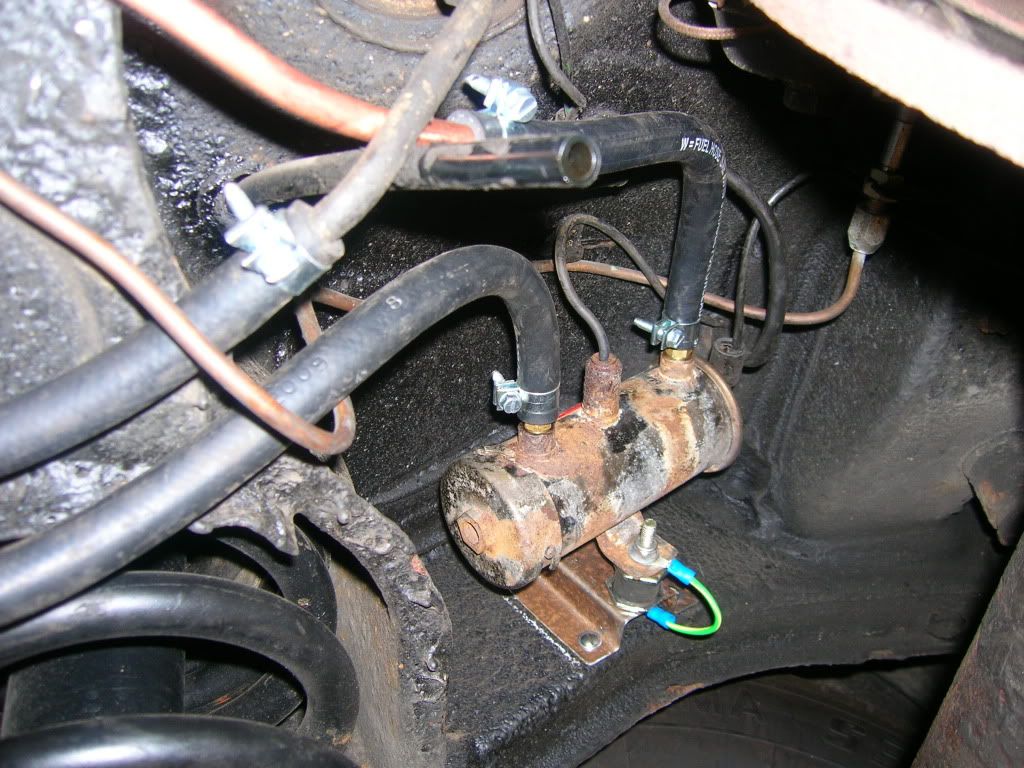
This fits neatly underneath the car and is screwed to the chassis with 4 self tappers. There's an earth wire needed from the pump the the body as the pump is mounted on rubber blocks.
The live wire follows the fuel gauge sender wire and goes up into the boot. From there it's threaded through the into the cabin behind the rear seat following the battery cable along the sill and up to the dashboard through and inertia switch and relay to the white wire in the ignition switch.
Back to the plumbing. The article describes how to reuse the original reserve tap by relocating it the back of the car. I still need to fabricate a bracket and lengthen the cable from the dashboard but you can see how it will work. Both of the pipes on the bottom of the tank need to be angled slightly to make smooth curves in to the reserve tap and the on to the pump. They would normally have pointed to the front of the car following the transmission tunnel.
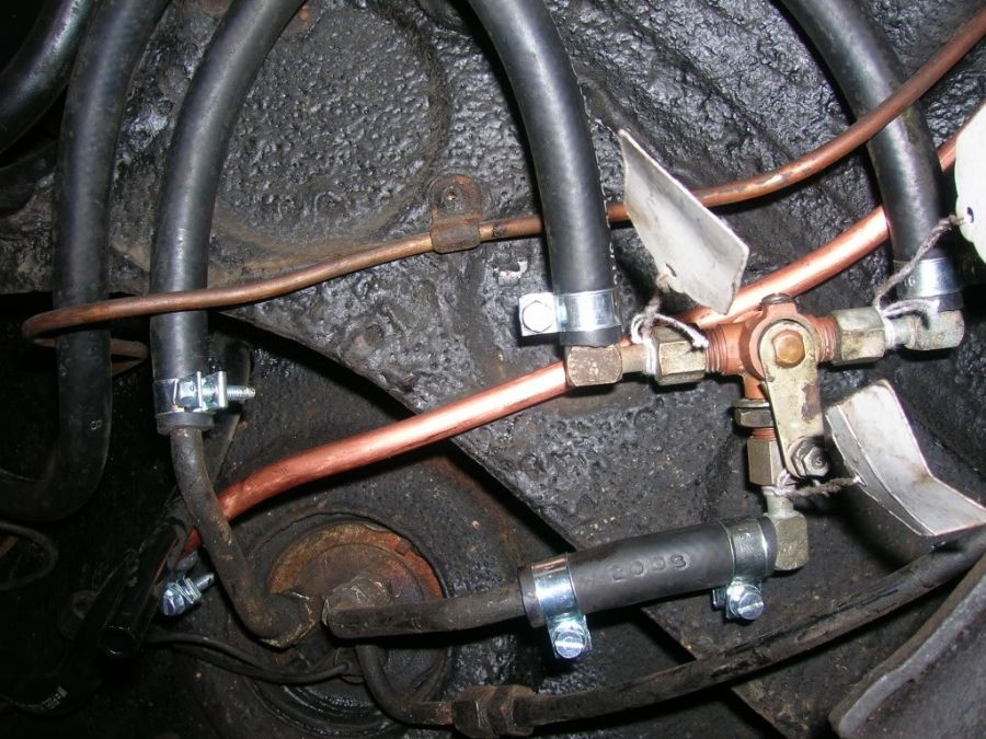
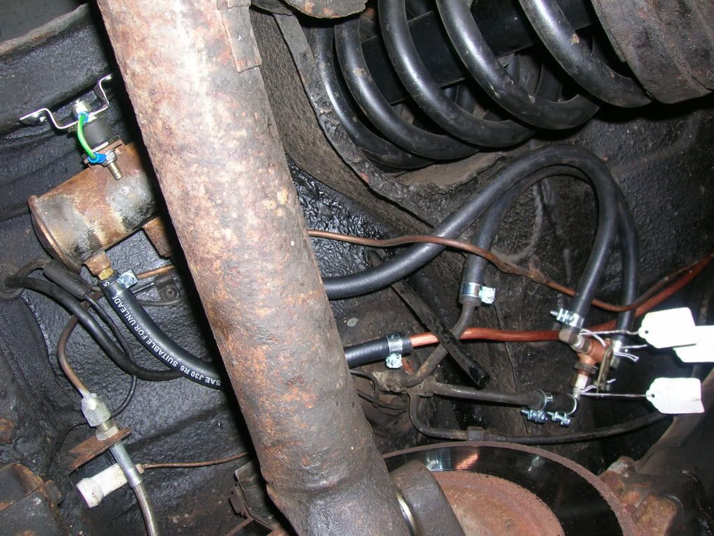
The majority of the pipe work is 8mm copper. This needs to be fed carefully through the heat shield at the side differential extension and then fastened into the clips alongside the transmission tunnel.
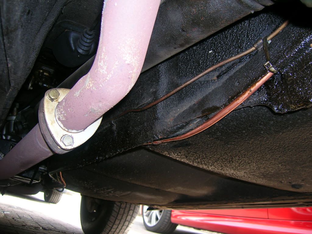
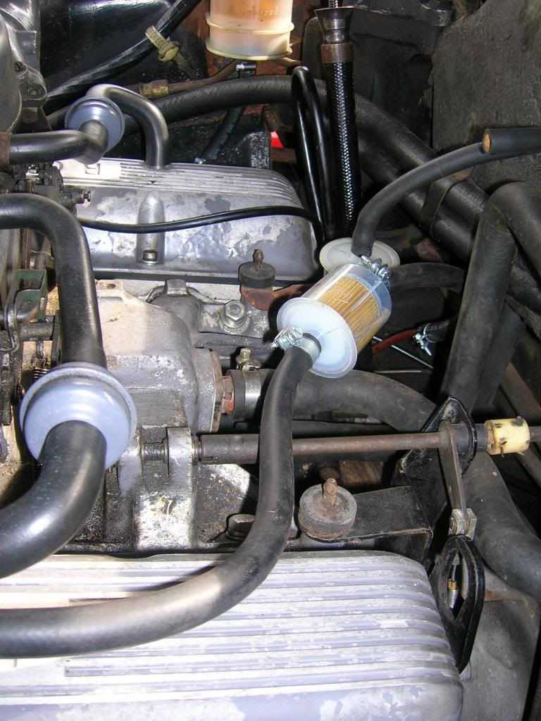
At the front, the pipe curves up the side of the bell housing past where the reserve tap used to be before changing to rubber hose and connecting to an inline filter on the way to the left hand carb.

Finally, here's the best picture I could get of the whole system under the tank. Since taking the picture, I've added a 'P' clip to the copper pipe to make it more secure.
Having done a few miles with this set up I can say its well worth the effort if just for the quicker starting. The pump is quiet and can only be heard when you're outside the car. The total cost was around £80 including the second hand pump.
There are still a few little bits to finish off, like the reserve cable and I'm not totally happy with the route the the rubber hose take over the engine and in to the carb. But, for the moment it works and that's the main thing now that the sun is out.
Thanks to Brian-Northampton for scanning the original articles, Ian at Rover Classics for the bits and advice, and finally, to Bob Russell who wrote club mag article which made it all possible in the first place.
The following Monday I had a couple of bits of good fortune. Firstly, there was a thread started by Mr Task enquiring about the ins and outs of the NADA fuel system where Brian-Northampton posted a couple of old articles from the P6ROC magazine detailing how to convert a UK car with AC mechanical pump to an electric fuel pump situated at the rear under the tank as on the NADA cars. Here's a link to the articles.....
http://www.p6roc.co.uk/download.asp?fil ... +23-28.pdf
http://www.p6roc.co.uk/download.asp?fil ... 2+8-12.pdf
Secondly, a quick call to Rover Classics got me most of the bits I needed to start including a used Facet Silvertop pump at a bargain price. Over the next couple of days I got some 5/16 rubber fuel hose, fuel filter and hose clips from a local motor factors and a length of 8mm copper pipe from Pirtek.
To start off I drained the tank and stripped off all the old fuel pipes but retained the connectors to be reused with the new rubber hose. The article in the club mag was written many years ago and suggests some of the parts, such as the pump mounting bracket, are available from you local Rover dealer.......so made my own. (i'll post a picture separately)
This fits neatly underneath the car and is screwed to the chassis with 4 self tappers. There's an earth wire needed from the pump the the body as the pump is mounted on rubber blocks.

The live wire follows the fuel gauge sender wire and goes up into the boot. From there it's threaded through the into the cabin behind the rear seat following the battery cable along the sill and up to the dashboard through and inertia switch and relay to the white wire in the ignition switch.
Back to the plumbing. The article describes how to reuse the original reserve tap by relocating it the back of the car. I still need to fabricate a bracket and lengthen the cable from the dashboard but you can see how it will work. Both of the pipes on the bottom of the tank need to be angled slightly to make smooth curves in to the reserve tap and the on to the pump. They would normally have pointed to the front of the car following the transmission tunnel.

The majority of the pipe work is 8mm copper. This needs to be fed carefully through the heat shield at the side differential extension and then fastened into the clips alongside the transmission tunnel.

At the front, the pipe curves up the side of the bell housing past where the reserve tap used to be before changing to rubber hose and connecting to an inline filter on the way to the left hand carb.


Finally, here's the best picture I could get of the whole system under the tank. Since taking the picture, I've added a 'P' clip to the copper pipe to make it more secure.

Having done a few miles with this set up I can say its well worth the effort if just for the quicker starting. The pump is quiet and can only be heard when you're outside the car. The total cost was around £80 including the second hand pump.
There are still a few little bits to finish off, like the reserve cable and I'm not totally happy with the route the the rubber hose take over the engine and in to the carb. But, for the moment it works and that's the main thing now that the sun is out.
Thanks to Brian-Northampton for scanning the original articles, Ian at Rover Classics for the bits and advice, and finally, to Bob Russell who wrote club mag article which made it all possible in the first place.

 priceless