

After a 265 Mile (427km) drive on Saturday, over which my Rover ran perfectly, the alternator then promptly failed. :shock: The ignition light remained off and the ammeter showed a discharge. The ignition light would also remain off when the ignition was switched to position 2, the opposite to what it is supposed to do!
Now the ignition light is connected in series with the field circuit within the 18ACR, so if the bulb fails, then the alternator will not charge. Checking the bulb showed it to be working correctly. The voltage regulator was swapped for another that I was carrying with me, again it did not fix the problem. Checked the brushes which were reasonably new, again they were fine.
I then removed the brush box so as to allow an inspection of the slip ring. All appeared to be normal, except when measuring the field resistance. A reading of 3.2 ohms is normal, but what appeared on the meter was a reading in the Megaohms :shock: .
I separated the two halfs of the alternator so as to allow a full inspection of the rotor, and then this was discovered.
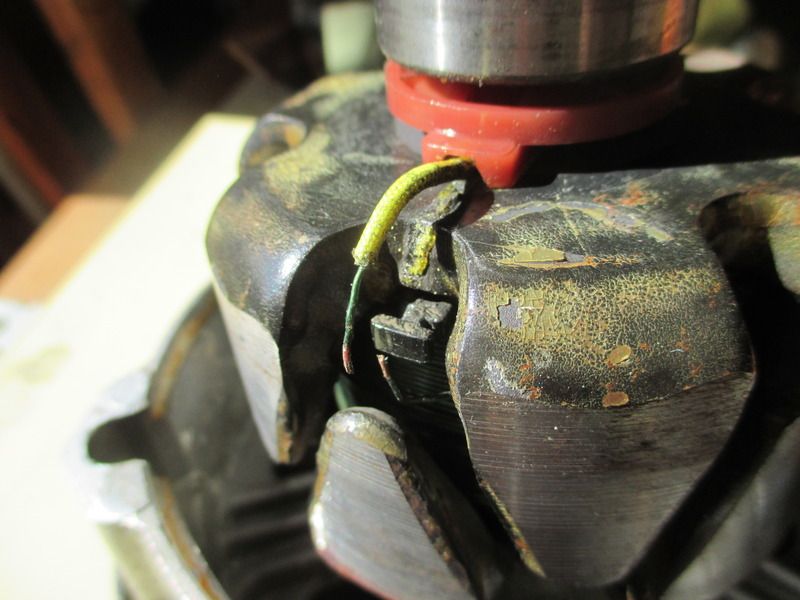
As can be seen, the winding had broken.
The wire was duly soldered back together prior to sliding a length of heat shrink tubing into place. Movement of the wire was then prevented by squeezing it into place around the 'T' piece, which can be seen in the photo behind the break in the wire.
Measuring the resistance again this time delivered the correct 3.2 ohms. Today another 265 Mile run, and I am happy to say that the alternator performed perfectly!
Ron.