Electric fuel pump inertia switch wiring

MJP6B

Member
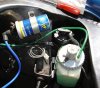
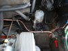
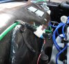
I am fitting a Huco electric suction fuel pump up front, behind the n/s headlights. I intend taking a ignition feed
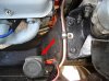
from behind the main fuse box (series 2 3500 S), incorporating a in-line fuse, a inertia switch (fitted just behind egg-box grille)
and a relay before the pump feed.

I would very much appreciate some advice from an electrical guru..............

My thoughts are that the inertia switch needs to be on the trigger side of the relay rather than the feed to the pump side, is this
correct ?

if so, where should I put the in-line fuse - in the ignition fed wire to the relay trigger or the pump feed side after the relay - or would it
be advisable to have a fuse on each ?

The plumbing is all sorted and 3/4 built ready for connection, but the electrics are giving me a headache, extra lights and other
accessories don`t phase me, but this I REALLY need to get right first time !

Thank you
 
Personally I'd put the inertia switch on the power feed to the pump so there's no question that the pump will be isolated in the event of an accident. You also need the fues in the pump's power feed too, so you should have - Relay > in line fuse > inertia switch > pump.
 
Hi, as testrider says. However unless you have the relay wired to the oil pressure switch
to shut the pump off in the event of an engine stall, I dont think you need the relay. The
pump doesn't draw enough current to warrant it, and you are putting some thing else in
to go wrong. It might also be prudent to put the inertia switch up on the bulkhead away
from the pump as car manufactures do, any impact that might damage the pump or its
fittings could also damage the inertia switch.

Colin
 
Thank you both Paul and Colin for your valuable advice. I will try it without the relay first - I only
included it trying to reduce any load on the sometimes "fragile" fuse box assembly, but as you say its another item that could fail and if its not needed why instal it :!: The in-line fuse next, and then the inertia switch before the pump positive terminal.
Since asking the question I have done a brief web search this evening on "position of fuel pump inertia switches" with varied results aligned with your suggestion, Ford favour the boot area, Jag/Honda passenger footwells and Land Rover engine bulkhead/firewall - my original thought of up front was way out, thanks to your advice I will find a suitable place near the steering relay/wiper motor area or possibly in the passenger footwell so that it may be accessed for resetting by opening the knee bin - got to have a look at the practical possibilities.

Greatly appreciate your input, thanks.
 
i got mine wired up from the ignition switch on mine then to a cut of switch then straight to the pump at the front works very well so i can turn it off when i dont need it
 
Hi Gareth, So your set up is purely as a back-up to the still fitted manual pump on the engine block, and is only used, I presume,when/if you suspect a fuel vaporisation problem? Logical and very sensible.
I am going fully electric with fuel lines as far away from the heat of the engine as possible, ie in the outer near side wing before going forward to the electric pump and feed to the carbs.
I get your point in keeping the OE system as long as possible, but I have 2 mechanical pumps all repaired ready to be fitted WHEN (not if) the existing fails. Twice in the last 10 years I have had to fit a replacement pump from my spares carried in the boot on the side of the road – the last time was in a bloody thunderstorm with my better half aboard and I vowed then never again !!!! The mechanical pumps fitted to the V8 were old technology when the V8 was fitted to the P6 and its a credit to them that 40 odd years later some are still going strong albeit thanks to numerous expensive repair kits( the existing pump fitted to my engine now requires an engine oil seal !- double :evil: .


All the best to the valleys.....
 
i not got a standard pump only a electric pump which that i use i have also moved the fuel line on mine away from the exhaust down side the inner wing here are a few pics
30857_386499694220_3401327_n.jpg

30857_386499699220_2501853_n.jpg

30857_386499704220_718829_n.jpg

30857_386499709220_507090_n.jpg


this way works very well as i said mine is wired straight to the ignition switch but i put a knock off switch in the line so when the car is not in use and some 1 hot wires it she wont run for long and keeping the fuel line away from the exhaust work great in traffic i put the fuel pump at the front as it's easy to get at
 
Gareth, Brilliant photos, your system duplicates mine in lots of respects, running exactly as mine does with one small
exception, I took my 8mm copper pipe all the way forward to where the wiring comes through the
wing to the n/s side/indicator lights (pure laziness on my part - did`nt want to drill another hole !)

I`m so glad your system works, the outer wing area is in the fresh cool air, and has to be so much
better at carrying petrol than a metal pipe hugging a hot engine block within inches of a red hot exhaust manifold.

I have moulded my copper pipe to shape but still have to fix and clip it into position and do the
connections, all electrics 90% done wired into ignition with a tell-tale LED (on the dash)spliced into the
pump side of a inertia switch to tell me if it has been triggered (going over a cattle grid too fast !) LOL
I will photo and post when commissioned.
Great input Gareth thank you.
 
yr welcome yea please upload some pics once you done glad that i might have helped you out abit
 
Great help Gareth thank you again.


As promised . Pictures of working Huco fuel pump, most aspects of conversion completed, system working and tested.

TEST: In hot weather late yesterday afternoon I simulated a traffic jam letting engine tick over for 20 minutes after a 3 mile moderate speed round trip (not hanging about), and engine did`nt miss a beat. :D :D

I have plans to make small additions to the installation, like a tin plate
heat shield adjacent to pump supply pipe to filter deflecting heat from the n/s front exhaust manifold and a stone guard plate inside the n/s wing to protect flex hose ( on second thoughts I may redesign this section completely)

PS: Have just noticed a drip from the clutch slave cylinder will have to investigate prior to Gaydon trip tomorrow :roll:


Part 2 follows:
 

Attachments

  • Snug fit supply pipe connected.JPG
    Snug fit supply pipe connected.JPG
    81.8 KB · Views: 1,380
  • Inertia switch fuel pump.JPG
    Inertia switch fuel pump.JPG
    77.7 KB · Views: 1,380
  • Inertia switch & pipe clip to strg relay.JPG
    Inertia switch & pipe clip to strg relay.JPG
    94.1 KB · Views: 1,382
  • In-line fuse to Inertia sw.JPG
    In-line fuse to Inertia sw.JPG
    63.7 KB · Views: 1,380
  • Pipe from reserve tap clearance throttle linkage.JPG
    Pipe from reserve tap clearance throttle linkage.JPG
    64.9 KB · Views: 1,382
Inner wing pipe assembly & fixings
 

Attachments

  • 8mm pipe & clips inside wing.JPG
    8mm pipe & clips inside wing.JPG
    101.9 KB · Views: 1,372
  • Forward end inside wing. Guard shield still to be made.fitted.JPG
    Forward end inside wing. Guard shield still to be made.fitted.JPG
    108.8 KB · Views: 1,370
that lookes brill that does remind me i got to re fix my pipe again to the bulkhead as when i took the pics i did not finish it off looks very nice i have now covered mine in underseal so it dont stand out lol
 
Back
Top