

You are using an out of date browser. It may not display this or other websites correctly.
You should upgrade or use an alternative browser.
You should upgrade or use an alternative browser.
Fitting a tachometer to a 2000 series 2 auto.
- Thread starter ajcb
- Start date
Pilkie
Active Member
Hi all.
Well ive just got a complete rev/clock pod to fit into the 2000 sc auto,so now I know what wires are what,it shouldnt pose a problem.
EXCEPT!!!
Its a 5200rpm V8 rev counter,so as it is presumably a pulse type "or is it" will it work ok on the 2000 4 cyl ??
Anybody fitted one to their 2000??
I will eventually get the correct 6000rpm rev for it,then I will sell the V8 one!
Dave
darth sidious
New Member
pilkie said:Hi all.
Well ive just got a complete rev/clock pod to fit into the 2000 sc auto,so now I know what wires are what,it shouldnt pose a problem.
EXCEPT!!!
Its a 5200rpm V8 rev counter,so as it is presumably a pulse type "or is it" will it work ok on the 2000 4 cyl ??
Anybody fitted one to their 2000??
I will eventually get the correct 6000rpm rev for it,then I will sell the V8 one!
Dave
Even if you were to wire it in correctly, it will under-read by half. It works on the pulses on the low tension circuit: -
Distributors run at half engine speed. Assuming 1000rpm (engine revs), distributor rotates at half that (500 rpm)
The 4-pot has 4 LT pulses for every revolution of the distributor, so at 1000 engine rpm, there are 500 x 4 = 2000 LT pulses per minute.
A V8 has, of course, has 8 LT pulses for every revolution of the distributor, so at 1000 engine rpm, there are 500 x 8 = 4000 LT pulses per minute.
If you were to wire it in, it would only register half the actual engine revs e.g. 3000 rpm on your 4-pot would only register 1500rpm on the V8 tacho.
As a slight aside, I am not sure how difficult it is to fit series 2 round dials into a car with a strip speedo. Again, how different is the wiring from a car with a strip speedo to one with the round dial instruments?
Pilkie
Active Member
I had a feeling it would read only 1/2!
At least it looks the part and I can practise my wiring up,so that when I get the correct pod/rev it will be a doddle!
Wouldnt know about wiring in a round dial dash to a strip speedo car!
Would of though its just a matter of mating the correct wires together,also the dash top needs to be swapped as well!!
darth sidious
New Member
pilkie said:I had a feeling it would read only 1/2!
At least it looks the part and I can practise my wiring up,so that when I get the correct pod/rev it will be a doddle!
Wouldnt know about wiring in a round dial dash to a strip speedo car!
Would of though its just a matter of mating the correct wires together,also the dash top needs to be swapped as well!!
Oh, I assumed (wrongly!!!!!) you had the series 2 round dial type!

You could try one of the methods suggested in this thread, but be aware it will under-read!
darth sidious
New Member
pilkie said:I thought you might of done,thats why I bunged a piccy up! :wink:
Glad you did! :wink:
ajcb
Member
Pilkie
Your POD is just like mine. Now that is no surprise.
The correct SMITHS tachometer has RVI 1000/19 ON THE FACE. RVI means it is counting the pulses in the current.
I see you have used the original clock from the car not the POD as the bezel is chrome. In the pod they were both black but some people have changed the bezzles on the POD rev counter and POD clock o they are chrome. They look better that way in my opinion.
But how about this http://cgi.ebay.co.uk/ws/eBayISAPI.dll? ... K:MEWAX:IT. Personally I prefer the strip job.
Incidentally I have concluded that for the negative earth of the 2 ways of connecting the tachometer the white pulse lead should be in series between the coil and the ignition switch (rather than between the coil and the distributor low tension terminal) and the green driver wire should come from the ignition switch.
Best Wishes and good luck
Tony Bunting
darth sidious
New Member
ajcb said:Incidentally I have concluded that for the negative earth of the 2 ways of connecting the tachometer the white pulse lead should be in series between the coil and the ignition switch (rather than between the coil and the distributor low tension terminal) and the green driver wire should come from the ignition switch.
In theory, either should work, but if it works better one way than the other, then stick to the one it works best at! The tacho we had was definitely wired between coil and distributor, then again it had an internal loop (and male and female bullet connectors), not an external loop.
Got it working, I take it?
ajcb
Member
Thanks for enquiring Darth. Not quite there yet on all the theory and probably won't physically fit it until the show season is over as I want to get up the M4O/M6 before I do the winter period jobs but have had a major breakthrough on the pick up points!
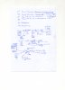
However I have got a lot further and realise I was wrong as to the best side side of the coil to fit the pulse lead although as you say it would fit either side. The reason for my change of mind is that although the Smiths documentation persuaded me that the tacho should be fitted on the positive side of the coil the P6 pickup points make it clear it is meant to be fitted between the coil negative terminal and the distributor. I have drawn a sketch of the four pick up points which I attach here:
In practice I will attach the two earth wires and the positive lighting wire to the existing earth and positive lighting clock wires.
My only outstanding matter is what type of wire to use for the pulse lead. Someone told me it should be at least 31 strand and 42 strand would be better. I am not sure of the amps or diameter of this wire. I think a tight fit where it loops through the pulse sensor twice is best but having tried a piece of 27 amp 42 strand 0.3mm square wire I found this to be too thick. I am also not sure what ampage the wire should be although I guess (yes guess) the amps are only about 5 so a 8amp wire would suffice. DO YOU OR ANYONE KNOW THE CORRECT SPECIFICATION FOR THE PULSE LEAD???
Best Wishes Tony Bunting
However I have got a lot further and realise I was wrong as to the best side side of the coil to fit the pulse lead although as you say it would fit either side. The reason for my change of mind is that although the Smiths documentation persuaded me that the tacho should be fitted on the positive side of the coil the P6 pickup points make it clear it is meant to be fitted between the coil negative terminal and the distributor. I have drawn a sketch of the four pick up points which I attach here:
In practice I will attach the two earth wires and the positive lighting wire to the existing earth and positive lighting clock wires.
My only outstanding matter is what type of wire to use for the pulse lead. Someone told me it should be at least 31 strand and 42 strand would be better. I am not sure of the amps or diameter of this wire. I think a tight fit where it loops through the pulse sensor twice is best but having tried a piece of 27 amp 42 strand 0.3mm square wire I found this to be too thick.
I am also not sure what ampage the wire should be although I guess (yes guess) the amps are only about 5 so a 8amp wire would suffice. DO YOU OR ANYONE KNOW THE CORRECT SPECIFICATION FOR THE PULSE LEAD??? Best Wishes Tony Bunting
Attachments
darth sidious
New Member
You seem to have it planned well!
I know I am harping about this, but be aware that P6's have different wiring, some of which the manual(s) don't seem to reflect/show. I'm not talking about the location of where to place the tacho loop, I mean that the described pick-up points are actually present on your car where the diagrams suggest.
I do hope you get it working. It was really useful to have a tacho on our car, even when we had to de-rate it back to SC status.
lakwandaphillips
New Member
darth sidious said:ajcb said:Incidentally I have concluded that for the negative earth of the 2 ways of connecting the tachometer the white pulse lead should be in series between the coil and the Ignition Switch (rather than between the coil and the distributor low tension terminal) and the green driver wire should come from the ignition switch.
In theory, either should work, but if it works better one way than the other, then stick to the one it works best at! The tacho we had was definitely wired between coil and distributor, then again it had an internal loop (and male and female bullet connectors), not an external loop.
Got it working, I take it?
I agree with this post. Decide which way works for you. As long as the tachometer is well-connected.