Rebuilding 3500S brake master cylinder

Rover2000nut

New Member
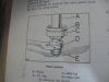
I'm back and more determined...i've put a new master cylinder in the car but looking at the old one trying to determine why it leaks even with the new seals in it.........the exploded view in the manual shows the plastic bearings and seals going one way yet the main piston image is exact opposite to the exploded view....i followed the exploded view but it leaked....the original was like the main piston pic and so was my friends cylinder when i took it apart....however the seal in the big bearing is turned inward in the bearing when the pics show the lip of the seal is outward.....what gives....has anyone taken theirs apart that can put me on the right track....which way is the right way

Thanks
 

Attachments

  • IMG_2936.JPG
    IMG_2936.JPG
    119.9 KB · Views: 671
  • IMG_2935.JPG
    IMG_2935.JPG
    94.6 KB · Views: 670
Hello Rover2000nut,

I have not had apart a 3500S master cylinder of the type that you have shown in the diagrams, so I will leave it to someone who has to help you regarding seal orientation.

Regarding the bore of the cylinder,..I assume it has been resleeved in stainless steel? There are no marks in the bore?

Ron.
 
It's not that clear, bit isn't the top pic the master cyclinder, and the bottom one the slave cylinder along with the air control valve on the servo?

Richard
 
quattro said:
It's not that clear, bit isn't the top pic the master cyclinder, and the bottom one the slave cylinder along with the air control valve on the servo?

Richard
My slave cylinder does not look like that. :)

Does anyone have a exploded picture of the slave cylinder (dual line)?
 
That is the exploded view of the NADA brake master and the piston pic from the master......The master only has one line (outlet) and an inlet hose, but the servo has the dual line...........if you look carefully a the 2 pics you'll see that the placement of the bearings 37 and 39 , with the seal 38 (lip in towards the piston bottom ortowards#33,34,&35) .....the main piston pic though shows bearing 39 placed the opposite way( thus the O ring 40 is on the other end also),so then 37 would be at the circlip end...the seal 38 i assume should still face the bottom or the same way as seal 34..........both mine and my friends when i disassembled them have the bearing positions like the main piston drawing but the seal (38) the opposite way......which is opposite to the exploded view.........i hope you can make out what i'm trying to say
 
My mistake, I am used to the girling system and didn't realise that this is the lockheed system.

It looks ok to me though

The top picture has

A - Piston
B - O ring
C - Bearing
D - Main seal
E - Spring retainer

In the lower pic, the same bits are

36 - Piston
40 - O ring
39 - Bearing
34 - Main seal
31 - Spring retainer

And they point in the same direction to me

Richard
 
Sorry...the 39 big bearing is recessed on the seal end to accept the seal but flat across on the non seal end so in the top photo the recessed end is towards the piston bottom yet in the main piston pic the recessed end for the seal is at the top which is the exact opposite way... i hope this explains it a bit better
 
Back
Top