REV Counter, help required, or perhaps I'm retarded.

Fraserp6

Member
Right, been at this for most of the day and I cannot see what the problem is.

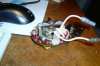
Since I bought my car the Rev Counter hasn't worked, now on the grand scheme of things there are plenty other things to get done on my 2000tc but today as I had the cluster out I thought... "why not"

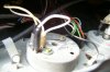
I have two bullet connectors, one male and one female, with the female one connected in series to a spade connector.

these wires connect in the car as follows.

Male connector through to bulkhead - White and Yellow Stripped wire.

Female connector to spade - White wire

Spade through to bulkhead - White wire

Once these wire pass through the bulkhead (and Narnia) they come out as follow.

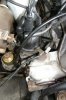
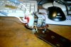
One THICK White and Yellow Wire and one THIN White and Yellow wire. These two wire marry up into the one connector and attach to the positive terminal of the coil, while I have a black and white stripped wire connecting from the distributor to the negative terminal on the coil.

This allows my engine to start, however, my rev counter is dead (as dead as a.....read what you like here) with no movement from the needle.

It's worth mentioning I removed my Rev Counter last night and checked it over with a circuit tester and the needle moves about just fine.

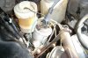
I have wires connecting up brake reservoir, which consist of two stripped black and white connectors married to the one spade connector, and one sigular black wire connected via spade connector. Are any of these placed incorrectly.

I won't lie, this is getting me a might p****** off.

Any comments of advice would be very welcome.

Fraser
 
Hi Fraser,

I hope a couple of your statement are wrong (or I've misunderstood). Can you check your Thick/thin yellow/white wires which you say come off the tacho to the +ve side of the coil. have you put a continuity tester on these wires to check?
{Unless of course on your car, the rev counter is taking its 12v feed direct from the +ve side of the coil??}

The positive side of the coil should only be connected to the ignition switch - it is possible that someone has been tinkering in the past and added additional connections to the +ve coil to add other electrical items. But it should only come from your ignition switch.

The fact that the -ve side of the coil goes straight to the distributor is your problem. The -ve side of the coil should go to the rev counter, and then from the rev counter to the distributor. As yours is going from the -ve straight to the dizzy, then you are bypassing the rev counter completely - hence it will be dead.

You need 3 wires connecting to your rev counter.
one connected to 12v
one connected to the -ve terminal on the coil
one connected DIRECTLY to the distributor.

Hope that helps.

Cheers,
Brian.
 
Right, that's starts to clear some stuff up, where do I get my 12v supply from? is there a lead connecting to the tacho?

also, say you wire everything back the way it was and now there is no spark coming from the plug, what have you nackered?
 
TBH I don't know where the 12v comes from, I've never looked at that bit, but yes one of the wires on the back of the rev counter should be connected to 12v.

You will continue to get a spark at the plugs, it works like this:

12v connected to the +ve side of the coil via the ignition switch (which is why it's called the ignition switch)
-ve goes to the distributor VIA the rev counter.
Points in the distributor make and break the connection in the low tension of the coil creating a High Tension voltage to the spark plugs. (through the physics of decaying magnetic fields)

All the rev counter is doing, is 'counting' the pulses on the low tension that is being created by the points in the distributor.

Why not:
Turn on the ignition.

Use your volt meter on the wires connected to the rev counter and find out if any of them have 12 volts. You should only have one!

If you don't have a continuity tester, use an ohm-meter and check for zero resistance on either end of the other wires to make sure what you think is the right wire coming out of the bulk head really is the wire your interested in. you might need to extend the wire with a bit of your own extra wire to achieve this as otherwise it's impractical. when you get zero resistance you know that each end of the wire that your testing is one continuous wire, and not two ends of two different wires.

Then we need to work out which wire should be the -ve coil, and which should go to the dizzy.

Brian.
 
Fraser,

I've just received yet another manual that I've bought off eBay which makes clearer the confusion that we've all got over your Rev Counter.

Rover changed their wiring so many times over the years, and whilst my car and your car are pretty much identical, our wiring is completely different.

In this new manual, I've a wiring diagram that must relate much better to your car, and surprise surprise, this one shows the white/yellow wires and also has the rev counter on the +ve side of the coil instead of the negative side!!

It looks like the two white/yellow wires on your +ve side of the coil are:
1. direct connection to the starter motor
2. connection to the rev counter VIA the ballast resistor

At the back of the rev counter, you have two wires, one white, one white/yellow.
The white/yellow is the other end of the ballast resistor
The white is your 12v source from the ignition switch.

In this arrangement, the -ve connection on the coil, does indeed go directly to the distributor.

Isn't it confusing!

Just to confuse matters more:
My 1971 model has the rev counter on the -ve side of the coil in series with the dizzy.
Your 1972 model appears to have the rev counter on the +ve side of the coil in series.
in 1973, they put it back on the -ve side of the coil, but NOT in series with the distributor!!

I'll see if I can scan this to a readable size and email it to you - I've still got your email address.

Regards,
Brian.
 
Right, that helps heaps, hopefully I can crack it tomorrow, the ballast resistor, where is that on the car? I keep thinking its the thing connected to my coil, however, thats the radio suppressor thing. The ballast resistor I hear Is a ceramic cylinder about an inch and a half long, any idea where I'm looking for it?
 
HI Fraser,

TBH I've never seen a ballast resistor, I think my car was a matter of weeks/months away from it being fitted as standard.

If you look at the wiring diagram that I've emailed to you, you can see the ballast resistor as the zig zag line between "26" the rev counter and "27" the ignition coil. Both wires joining this ballast resistor are marked WY for White/Yellow. From what I've read on this forum, I wouldn't concern yourself with finding a "thing" that you can label as the ballast resistor as it's usually just a wire. But a wire with a resistance that will reduce your voltage to the coil from 12v to about 9v (IIRC).
The important thing is that a white/yellow wire at the tacho end and appears out of the bulkhead as a white/yellow and if you put an ohmeter across it, you will measure a resistance (not zero) but will show that you have both ends of the same wire.

I would suggest that with the ignition on (in the number II postion on the ignition switch), you should show 12v on the white wire at the back of the tacho, and about 9v (ish) on the white/yellow wire going to the coil (disconnect it for the test).

I am wondering if your white wire at the tacho, has been connected to the white/yellow wire through the bulkhead to the coil and bypassing the tacho and ballast resistor, for reasons as yet unknown. Worth exploring the possibility. An ohmeter across the wires will tell you this. a Zero Ohm reading says your connected to the same piece of wire without a ballast resistor inbetween. and infinate reading says your connected to different wires!

When you next look into this problem, can you take plenty of photos and post them so that we can see what you're seeing please?

Hope this helps,

Regards,
Brian.
 
Thank you for your wiring diagramme, a great help, if it wasn't pelting down with rain all this week I'd have probably got the car sorted, no such luck.

Having more or less understood the wiring, I think I might be best replacing all the wires from the ignition onwards, basically making up my own primary circuit. There are so many dodgy joins and random Ford connectors in the engine bay that I might as well just start from scratch.
 
Right, so it may have become obvious by now that electrics are something I fail to understand even on the most basic of levels. In my impatience I have managed to prevent my car from running all together. Spark plugs have been taken out so see if its a dizzy coil, no sparks from the plugs.

Taken off the main lead from the coil to the Dizzy, no spark when thats next to the block, so I assume its the primary circuit I've damaged, though I don't know how to make sure. I've purchased a Gunson Multi-meter, though in all honesty I am too stupid to use it as it just seems to be full of symbols.

So to summarise, I don't have a spark, I don't have a rev-counter still, the car does crank over, so its an ignition problem, I can't see any broken fuses.

Pictures to follow, uploading them just now.
 
If your not getting any HT spark, next thing to maybe test is the low tension (LT) connection at the front of the dizzy. It should have 12 volts on it when the ignition is on and the contact breaker is open. To test it with you multimeter, just switch the meter to Volts (V) range, connect -ve meter lead to ground (e.g. engine block) and the +ve meter lead to the dizzy low tension spade connector. You don't even need a meter. A 12 V bulb or test lamp will do - the bulb should light with the contacts open and the ignition switched on.

If you have been working on rev counter wiring you might have broken the LT feed to the dizzy that goes via the ignition coil?
 
Rigth well today it hasn't rained, so a productive start, so I set about testing every circuit in my car, to see what the problem was. I finally found why my Rover had not been running. The tiny thread like wire that runs from the distributor casing to the fixing inside the dizzy shared with the capacitor had burnt through, replaced it and my engine now starts and fires over fine, in fact damned well after a new set of HT leads and plugs, HT I may add that are FAR FAR too long.

I still, however have no rev counter, so I think I'll go over it all to see what the problem is.

These are my thoughts.

The Yellow and White wire from the starter pairs up with the Yellow and White wire from the tacho to the connection at the positive terminal on the coil. There is then a Black and White wire to the coil coming from the dizzy to provide a pulse reading to the Rev Counter. Either of these wires disconnected and the engine will not spark, simply tick over.

I am concluding then, that there is probably a problem with the white 12v feed from the ignition to the Rev counter, as if the engine starts and the Rev Counter is still dead, the yellow/white wire from the starter must provide power for the Primary Circuit in the coil? Yes? No?

If the White wire from the ignition provided power to the rev counter then to the coil then no movement from the Rev Counter would surely imply no movement from the entire engine? Therefore I'm concluding that power from the ignition and the Rev Counter are taken from two separate points?
 
Hi Fraser,

You've almost got it. So long as the wiring in your car is the same as the latest diagram that I sent you.....

The yellow/white wire from the starter motor to the coil will only provide ignition current while you are cranking the starter, not when the engine is running.

When the engine is running, the white wire 12v source provides the current to the rev counter, then from the rev counter through the ballast resistor to the other yellow/white wire on the +ve side of the coil during normal running.

The -ve side of the coil goes to the dizzy.

If your white wire was faulty, your engine would not run after starting. You could test this by disconnecting it and then trying to start the car! (but make sure it is isolated/insulated, you wouldn't want this wire earthing!!!!!

The reason it works like this is that you should have a 9 volt coil on cars with a ballast resistor instead of a 12 volt coil on cars without a ballast resistor.
Then when trying to start the car, on a freezing cold Scottish winters morning with a battery half flat, the fact that the starting ignition current bypasses the ballast resistor means that you're shoving a full (hopefully) 12v through a 9v coil and getting one hell of a fat spark! The car starts and immediately switches to the normal wire going through the ballast resistor which lowers the voltage to 9v through the coil. If you continued to run 12v through a 9v coil, the coil would quickly burn out your condensor in the dizzy (been there and done that!)

Having described that, what do the connections look like on the back of your rev counter - can we have a photo please, and also some pics of the other wires that you think are connected to them..

Brian.
 
Pictures as promised
 

Attachments

  • S4200001.JPG
    S4200001.JPG
    60.6 KB · Views: 566
  • S4200003.JPG
    S4200003.JPG
    63.3 KB · Views: 567
  • S4200005.JPG
    S4200005.JPG
    55.4 KB · Views: 565
Hi Fraser,

Well that all matches the circuit diagram, and with these rev counters, you can't wire them up incorrectly. One is a spade, one is male push connector and the other a female push connector.

So.... back to the basic question. Why do you think that the rev counter isn't dead? I remember you saying you'd done some test on it, but if the wiring looks to be correct?????

Brian.
 
I took my Rev Counter out at some point and tested it with a circuit tester, as I tested the counter with a circuit tester, the needle jumped up and down, to various degree, depending on how frequently I tapped the counter.

You think there may be an issue with the counter or perhaps its contacts itself? rather than an issue with the wiring?
 
Hi Fraser,

What sort of circuit tester was it?

If anyone else on the forum can help here, please chip in.

In theory, I would have expected that for your 'tester' to have made the needle jump about in a way that would show that the rev counter worked you would have needed to:
a. supply a voltage of about 12 volts
b. make/break contact of the voltage with the rev counter at quite a rate - if you think about it, to register only 100 RPM on the rev counter, you need to simulate 100 revs of the engine. The dizzy rotates at half the speed of the engine which is 50 revs per minute and in that 50 revs it is making/breaking the contacts at the points 4 times which is 200 make/breaks per minute or 3.5 per second. Were you doing this with a 12v source and what readings did you manage to get.

****Can anyone on the forum confirm that my maths is right...... ***

Brian.
 
Yeah Brian, you're right with the maths, I was using two 1.5volt batteries connected to a bulb and wires, when the rev counter was connected to the circuit tester, which is a purchased item, not something I knocked together with duck tape, the thing raises to about 5thousand rev, then as you break the circuit the needle falls again. If you then tap the circuit agin, the needle will rise, I imagine doing this rapidly enough, you'll get your rev reading. I was being perhaps a little optimistic with my description.

Still, finished up for the day, Got a current going through the white wire, my white and yellow wire and a pulse heading through my black and white wire, so perhaps the fault is with the contacts going into the Rev Counter. Back at work for the week, so will need to crack on later on.
 
Right so its that time of the week again where I have the two days off to work on my Rover, seeing as the girlfriend is travelling Europe at the minute, the entire duration of my two days can be spent on my 2000tc.

Below are photos of my REv counter, taken out of the casing and the bare guts exposed. I have two very fragile springs, one which pull the spindle, which the needle attaches to up the revs (around) and another that pushes the needle down the revs (around). I also have my two bullet connectors wrapped around a item I can only describe as a "electric motor type thing" with very narrow copper windings, then connected to a bi-metalic strip, which I assume when a current is passed then grounds the base of the counter and thus completes a circuit allowing the counter to work.

The previous week I was bypassing this with a circuit tester which was why I was getting movement from my needle.

The question I ask is..... has my "motor type thing packed in?" or the bi-metallic strip? If so, are they economically replaceable and can I get one from Maplan haha.

Feedback would be appreciated on this

Fraser
 

Attachments

  • S4200013.JPG
    S4200013.JPG
    56.1 KB · Views: 392
  • S4200014.JPG
    S4200014.JPG
    59.4 KB · Views: 392
Hi Fraser,

I bet you could get this http://cgi.ebay.co.uk/rev-counter-f...s_SM?hash=item3354745454&_trksid=p3286.c0.m14 for 99p plus postage. Why not try it out to elimate the rev counter itself. Assuming that this one will work!

If you look closely at the picture, it looks like it says "RVI" in small letters at the very bottom. I believe that so long as yours also says RVI, then they're interchangeable. If yours says 'RVC' then they're incompatible. RVI senses current, RVC senses voltage.

Bri.
 
Back
Top