1970 Rover 3500 - EMF

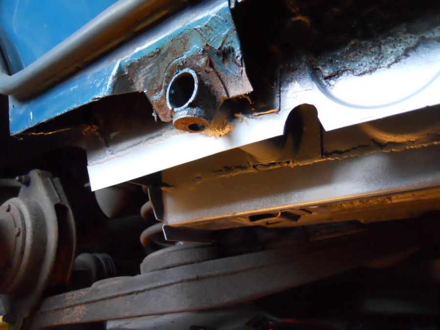
As I had the sill panels made before I knew how much I was going to cut off I ended up with a few gaps to fill in so that I had a fairly straight line to weld to. This also meant that I could weld the jacking tube to the sill too.


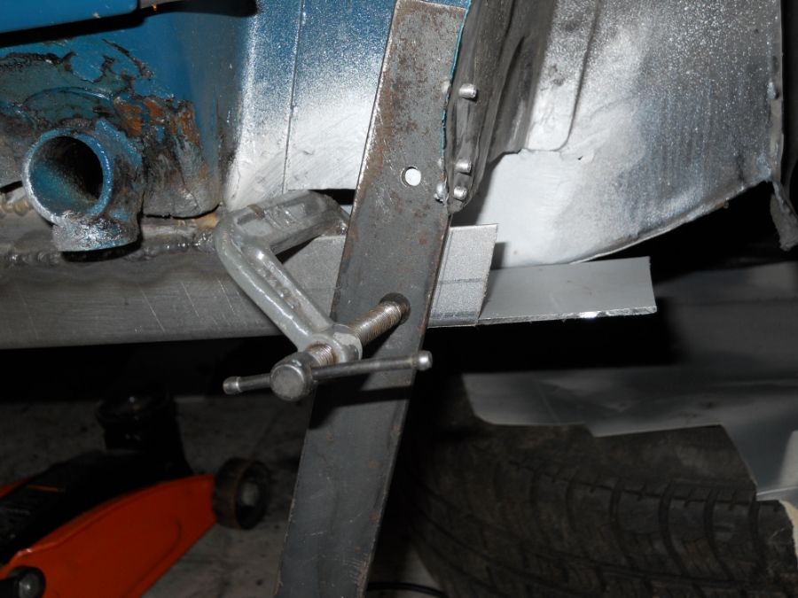
Next step was to create the spot weld flanges on the end of the sill which hold the rear wheel splash panel in place.


Trial fit and tack in place.


All welded up, I'm pretty pleased with how that's turned out.


I deliberately left the front of the sill long so that I could form the spot weld flanges in situ to get the angle and positioning right.


Everything's there for a reason.


All done.


More bits to fill in at the back.


I've just got the front splash panel to make and weld in, bit of paint, refit the interior and we'll be ready to hit the road to Bowes Museum next weekend. I'll have to sort the jacking points and B post bottom when I get back. Oh, and the other side too.....
 
Nice neat work Paul,
You have caught that at the right time when there is still plenty of good metal to work from.
I have adopted the same technique for my sill repair to retain the circular pressings - only having to cut further for that good metal!
Are you going to inject wax into sills when complete ?

Mark.
 
Thanks Mark. When I drill the holes for the screws that hold the sill cover on I'll spray some more etch primer inside to protect it this weekend and I've got some cans of Dinitrol to spray in too, but I won't do that until I've finished the jacking points next week.

It can seem a bit pointless trying to retain all this little pressings and folds when we're weld fairly large sheets of steel next to them but they do make the panels stiffer. When I added the stepped edge to the sill repair panel it became stiffer along it's length and it's also able to resist vertical loads better.
 
Paul,
Slight tangent - I am considering altering the jacking points so there is also a vertical 'box section' passing through to below underside of sill.
This could then have a 'pad' fitted (like modern Mercedes etc) and could be used for raising without fear of floor being damaged by tyre fitters / MOT inspection.

Mark.
 
Very impressive work there Paul. It's not easy working with slightly thicker gauge steel (as you've found out) but the final result will be well worth it. Have you considered drainage holes in the sills? I know it's been mentioned on other threads where people have rebuilt the sills only to have them fill up with water that has nowhere to go.

Dave
 
drabbers said:
Paul,
Slight tangent - I am considering altering the jacking points so there is also a vertical 'box section' passing through to below underside of sill.
This could then have a 'pad' fitted (like modern Mercedes etc) and could be used for raising without fear of floor being damaged by tyre fitters / MOT inspection.

Mark.

Actually Sowen made some of those for his P6 Muscle Car/Turbo TC project. I can't find them in his thread, but I copied the photos ages ago.


I'd intended to do the same here, but I've got a time restriction on this project given that my TC is off the road too and I'm meant to be renovating my house. I think the standard jacking points are plenty strong enough for wheel changing now and the sills are thicker than before so a trolley jack and block of wood will be fine in the garage.

Dave3066 said:
Very impressive work there Paul. It's not easy working with slightly thicker gauge steel (as you've found out) but the final result will be well worth it. Have you considered drainage holes in the sills? I know it's been mentioned on other threads where people have rebuilt the sills only to have them fill up with water that has nowhere to go.

Dave

Definitely having drainage holes Dave, I was thinking about 10mm diameter ones on the folded edge in between the sill cover screw holes.
 
Thanks for images Paul - that's just the type of set up I had in mind.
Ref EMF sill drain holes - the 1980's Rolls / Bentleys had galvanised sills with rubber 'vents' on flat lower edge and for some reason they can rust out quite badly.

Mark
 
Sorry - I haven't worked out how to highlight the 'conversation' for reply yet !
I meant the sill drain holes discussed for EMF.

Mark.
 
Boooo! :(


That's two recovery trucks in 3 months. The front bearing in the alternator collapsed and so the shaft wouldn't turn.
 
Bloody alternators. At least it'll be an easy fix.

If you fancy selling the Green car, I know someone who might be interested.. ;)
 
unstable load said:
Oh no! What happened?

The front bearing in the alternator failed so the shaft stopped spinning.


I'll pick up a new one this afternoon so I can put the alternator back together later.
 
I've just changed mine, Paul.

Make sure you put the various spacers/washers back in the right order. When putting the bearing in the front housing, put the thin spacer in, then the seal, bearing, thicker spacer & then circlip. I put the thick spacer between the bearing & the front housing & couldn't work out why the armature wouldn't spin when I tightened everything up! It took around 7 attempts to work out that everything was being tightened up too much! :oops:

Also press the rear bearing fully back into the rear casing.
 
Thanks Phil - still took 2 goes to get it right.

It's back on and working now, but under full electrical load and with the engine at constant 2000RPM the ammeter swings rapidly between charge and discharge. Does this mean that the current isn't being rectified properly and a diode(s) has failed? It did it a bit before, but now it's more pronounced.
 
Hi Paul,

From what you describe, that definitely sounds like a regulator problem, especially given the overcharging.

If one of more diodes within the rectifier should fail, then the tell tale sign is an ignition light which will glow dimly, fading out altogether by about 2000rpm. The ammeter however will offer no indication of a problem being present.

Ron.
 
I've been a bit slack at updating this thread recently, but I have done a few jobs on the car including finishing off the driver side sill replacement that I started in May.

You might remember I was trying to replace the sill and get it on the road for a weekend away in May and the last pictures I posted were of the sill welded in place. I managed to get 2 coats of Epoxy Mastic 121 on it before we went away but I didn't finish the jacking points or the closing panel on the bottom of the B post and I left it looking like this.


That got the underside strong and waterproof so I could use it throughout the summer. You can also see the drain hols I cut into the bottom corner of the sill.
 
Back
Top