3500EI

Just seen this properly on the news this morning - Looks horrific - hope your friends and family are all safe!

THX Rich, all friends report as being "shaken but not stirred" + my only personal issues now are electricity stoppages + supermarkets running low on food, all temporary + the very least of anybodies worries here, certainly compared to the poor folk in Miyagi-ken who bore the brunt of the quake + tsunami

( Apologies to Al for my inadvertent thread hijack )

GW
 
Right. Progress! I have found a few more magazine articles on the AE Brico injection. One from 1966 describing it's operation with lots of schematic drawings but no photos so I suspect that '66 was very early days and no worthwhile prototypes were up and running. Another from an American magazine from '68 on electronic injection generally which mentions the Brico system and has several photos of the Rover 2000 FI system's components. It also states that Brico had running systems on the Triumph 2000 and Ford Cortina though the manifolds on these are quite crude compared to the Rover one.

You can see from the photos of mine that the breather system is not going to line up with the standard P6 pipes, however it does line up perfectly with an SD1 type breather screwed into the oil filler hole of a rh rocker cover used on the left so I'm having a play with that now.

Also, excellent news! The guy I bought the system off has found the correct distributor so that should be winging it's way to me as we speak. :D 
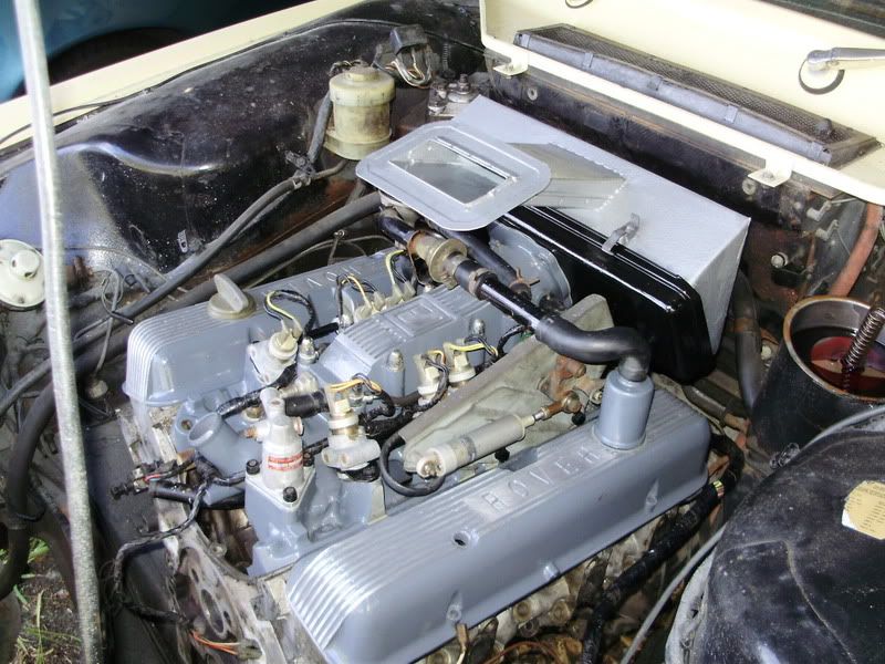
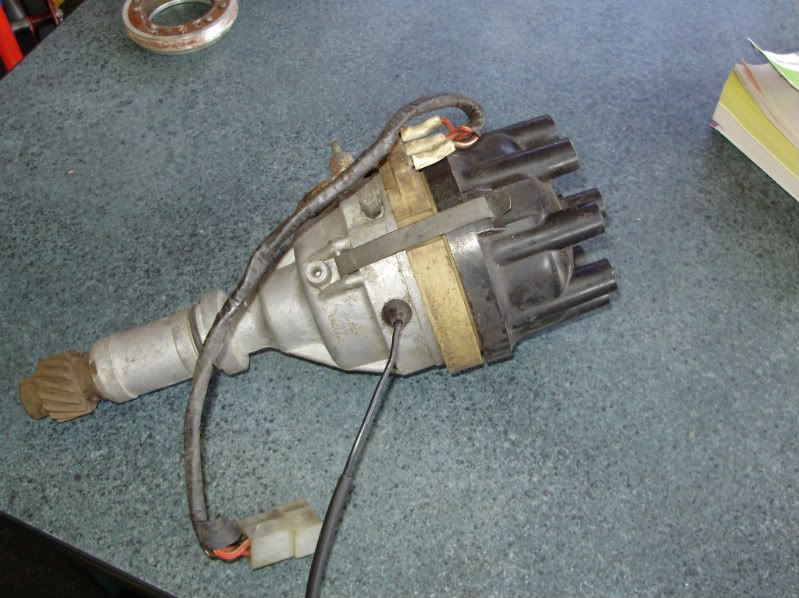
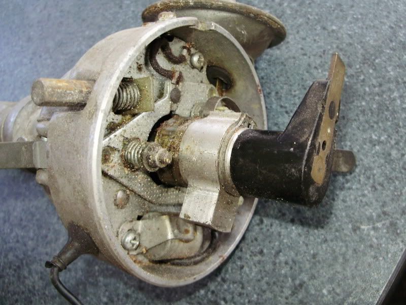
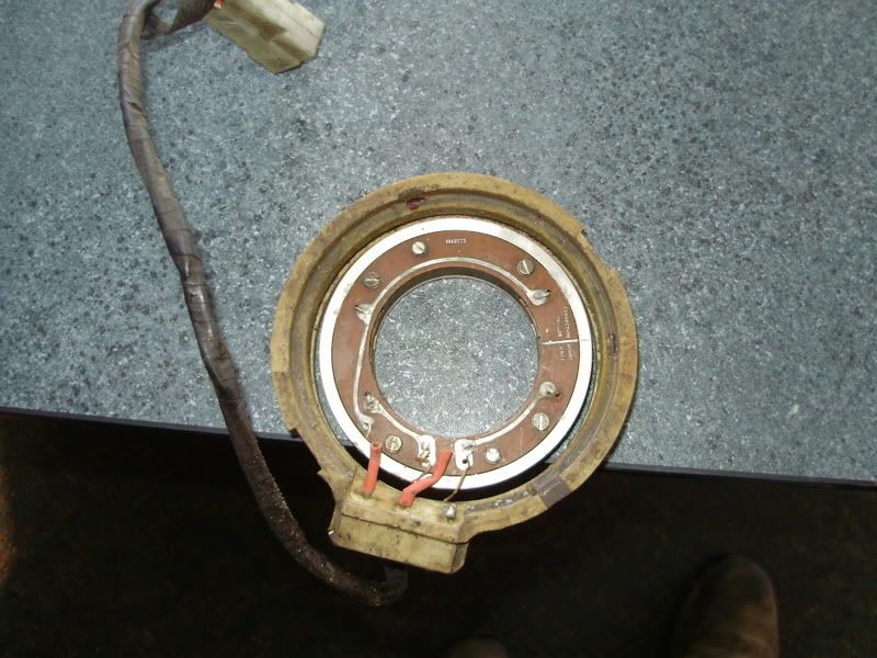
It looks to be a normal dizzy but it has a plate sandwiched between the body and cap with a pickup and some wires coming out to the correct plug. :D :D :D :D :D
 
fantastic news, and as good or better than a lotto win!!, good progress, we may yet see published performance figures for a system that never was :LOL:

graeme
 
Wow, thats' fantastic news, Al!

I can feel you being within sight of a trial fit!

Almost time to start getting the badges sorted out!

Chris
 
It's getting dangerously close Chris. I've got a spare 2200TC air cleaner that I think I can chop up, the throttle linkage will need some creativity (the actuator rod needs to be pulled back towards the firewall) and that leaves the fuel pump and filter which shoud be easy. The 2000FI used what looks like a Triumph PI pump but running at a much lower pressure. I may just go for a generic pump though. Is there a straight high pressure replacement for the Bendix? Also, how much pressure can those plastic fuel lines take?
 
You may have to start investigating some custom aluminium castings soon, I would expect a lot of demand were it available as a kit item.
 
Any idea what pressure the system requires Al? The injectors look pretty standard so it must be worth a punt just using a pump off any old injection car.

Why not trial with a jury tank to start with. Then you could use a Range Rover type in tank pump. There's bound to be a bit of creativity required with return lines, tank breathers and so forth, so perhaps best not to mod the existing fuel system until you're confident what is required.

I think the issue with the current fuel lines is more likely to be to do with age than design pressure. Chances are a revised system will be required anyway.

Chris
 
The 4 cylinder book says 25 psi which isn't much really. All the injector lines on the manifold are made of the same plastic so they should be up to it. I don't think there should be too much modification to the fuel circuit, remember the car already has a factory electric pump and the standard return line should be adequate. Tank breathers shouldn't need to be changed but the manual shows a swirl pot fitted around the pipes inside the tank.
I guess swapping the plastic line for a steel or copper one should be easy though. Did all the injected Rangies have an internal fuel pump or did some have an external. I've just been looking through a Rangie manual and it looks like the carb'd ones had a suitable looking fuel filter with replaceable element so i'll try and track down one of those.
 
A friend of mine is building a cheapskate Mazda 929/RX-4 coupe as part of another forum challenge (13's for $1,300). He's just bought some aeromotive high volume fuel injection pumps along with an interesting device which we didn't know about - basically it's an Aeromotive pump controller that controls the pump output so that the pump isn't working flat out all the time and hence, less of that annoying noise that a lot of aftermarket pumps have. He's going to try using the setup in lieu of a surge/swirlpot tank. Maybe something similar would suit this setup?
 
A few bits of progress. I have made an air cleaner for it using the shell of a 2200TC air box and a bit of steel, and the distributor arrived yesterday. It needs a bit of work, it looks to have had a rubber mount holding the centre sections in place but that has completely disintegrated so I'm trying to find a square section 'O' ring to do the job. Then just need to solder the wires back on and it's done. Unfortunately I don't think I'll be able to use my electronic ignition with it. :(
Pictures to follow. :)
 
OK, piccies. First up is the air cleaner. I started with a 2200TC unit but with the base, I cut out the section that bolts to the carbs and replaced it with new steel which was then drilled to suit the intake. The upper half of the air cleaner was cut off about an inch up from the flange and a new box was folded up and welded on. The snorkel was made from scratch too but may need a bit of tweaking to match the bonnet hole. It was then painted with Hammerite and fitted with a new filter. It'll do for now.
P3230133.jpg

Then the distributor arrived. Basically it's a standard dizzy with an extension.
P3230126.jpg

Inside is an aluminium extension attached to the shaft with a pickup thingy in the back of it like so..
P3230124.jpg

The clever bit is this bit of gizmo which has two opposing pickups in it and 3 wires. The bad news is that the inner part should be attached to the outer part by what may have once been a rubber ring. I'm hoping that a square section 'O' ring will do the job, then the wires just need to be soldered back on.
P3230120.jpg

Also heard back from James Taylor today with a very interesting bit of news. :wink:
 
That distributor is definitely an Ooohh Err Missus! Am I missing something obvious, but I can't see how either points or a trigger are going to be mounted in there. I'd have expected some sort of a block containing the trigger to be mounted onto the PCB to align with the alloy trigger on the shaft? And is that points I can see just peeking out round the back of the shaft, or does the electronics provide the signal to the coil?

Wasn't it just fortunate Mr Malvern realised what he had in his shed!!

I like the filter housing you've created. That looks to be within a gnat's c###k of what is pictured in Taylor. I don't think either the filter housing or the "plenum" are going to provide anything like the airflow potential of the later SD1 / Range Rover Lucas system though. Once done it would be interesting to put it on a rolling road and see what it delivers. For comparison a standard UK spec auto is reckoned to produce between 95 and 105 at the back wheels. (you can't gemerate a flywheel figure because the dear old Borg Warner doesn't have lock up, so you can't get a decelerating resistance figure to add to the power figure)

Chris
 
Fairly self explanitory, the sparky thing is standard and the injectors will have 2 coils (reluctors) to control the solinoids. Have you dissasembled the coil pack yet? Though quite how you get the required number of pulses from just 2 pickups alludes me at this point (lack of knowledge on my part of old injection systems). I suspect the 2 coils have laminated soft Iron cores that poke out in the right places to get interupted by the spinning iron thingey

Great stuff super keen to see more, it all reallly looks the mutts nuts.

Graeme
 
Hi Graeme.

No coil pack here! The system seems to use the standard, points ignition, coil - see the picture earlier of the installation in a prototype car. What I'm not clear on is how this system triggers that coil. Does it reatain a set of points, perhaps hidden behind the shaft in the picture?

What also confuses me in the distributor, is that I can see an electronic board and I can see a shaft mounted metal lump, but I can't see a detector on the board to complete a hall effect signal generator. Also there appears to be only one trigger point per revolution of the distributor. Does that mean the injectors are fired as a block of eight twice per 4 stroke cycle?

Chris
 
Hi Chris the coil pack I am refering to is the coils in the pc board assembly, the rotating lump on the distributor shaft is a magnet, (think magneto), you can create multiple pulses by having the iron laminated core of the coils shaped so that they react with the magnet at different points about the circumferance that the magnet passes thru.

Graeme
 
Oh, I see! I'm used to the magnet being on the stator! I can see the laminations on it now. And therefore, yes, two pickups on the board. That makes complete sense, because you then have each bank of four injectors fired twice per complete cycle. A lot of modern cheapy injection systems still do that!

Chris
 
Yup, that's basically it. Two pickups on the circuit board so the injectors are fired in batches of four. I believe the lucas system was the same. The standard points are still there, just visible behind the shaft. The ignition is controlled by the points while the reluctor pickup controls the injectors.
 
Back
Top