

Geordie Jim
Member
I think you are referring to this.
http://www.disgruntledgoat.com/content/ ... F4HP22.php
the seal to the A clutch can allow pressure to hold the A clutch engaged. Apparently there are Teflon seals to replace the steel ones.
Both boxes I stripped did not show signs of this., time will tell,,,,,,
It's a RPITA to get the bolts through one flex plate ( 50mm hole) through the next flex plate and then into the torque convertor.
Warren,
The existing mounts foul the box and are too far forward to use.
Jim.
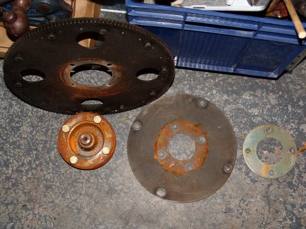
 I think the only bit missing is the 6 bolt/4 hole