My mean green hornet

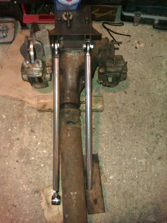
Since the last update I've fitted the second set of Outlaw calipers which have larger pistons and are in much better shape.
They needed 6mm lug spacers to centre over the vented disc perfectly. I will add some photos soon.

Diff, 3.5 engine, v8 prop, smaller piston outlaw calipers all now sold.

In other news I've begun work on my gauges idea.
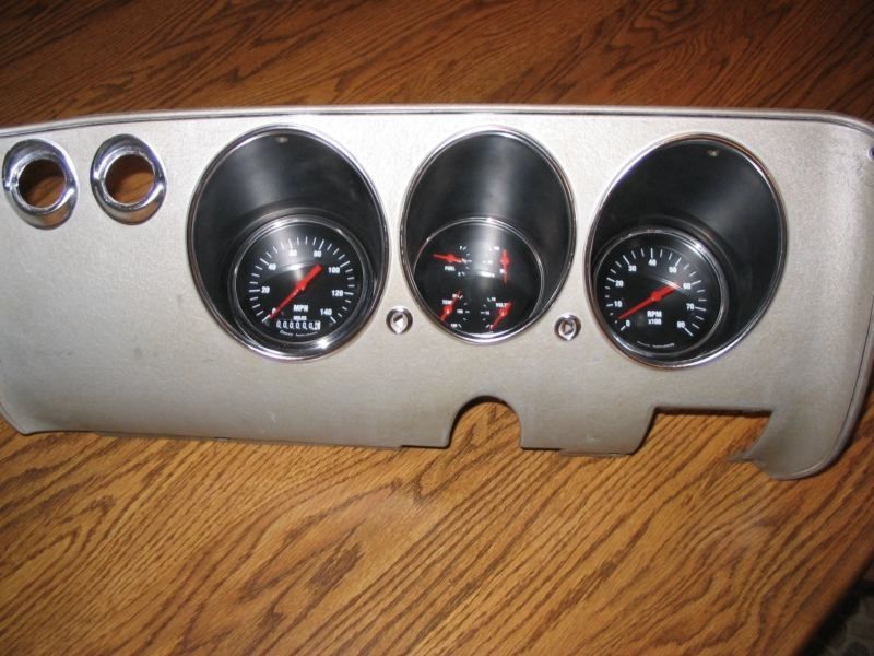
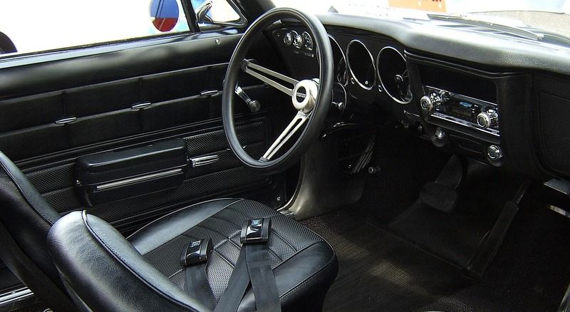
I ended up buying a Corvair Monza dash pod like this


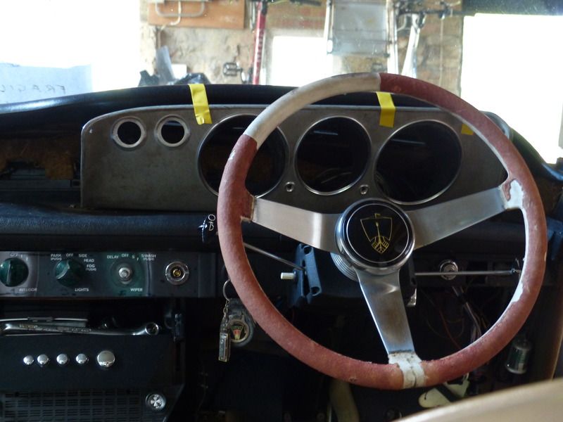
I've made the first modifications after careful consideration of whether to cut the part or the car.
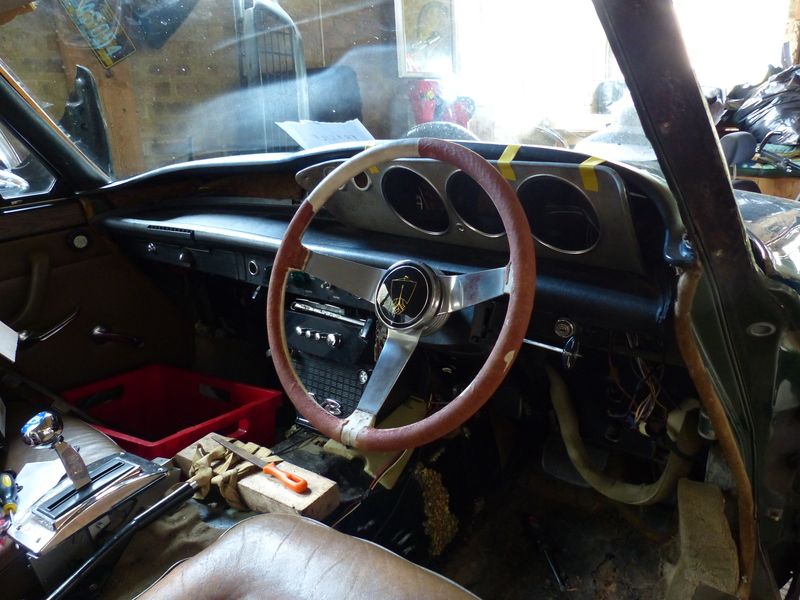
A few inches trimmed off the lower edge of the corvair pod and re-bent under it now can begin to take shape in the stock gauge cluster location.
The right hand side upper edge will need trimming to follow the dashtop lines but the left will fit rather well.


Ultimately the body of the pod will be black, and I'll re-polish the bezel rings. Something along these lines


The gauges I'll be using are Veethree Black Sterling and include GPS Speedo, Tach, and 4 in 1 Fuel,Water,Voltage,Oil.


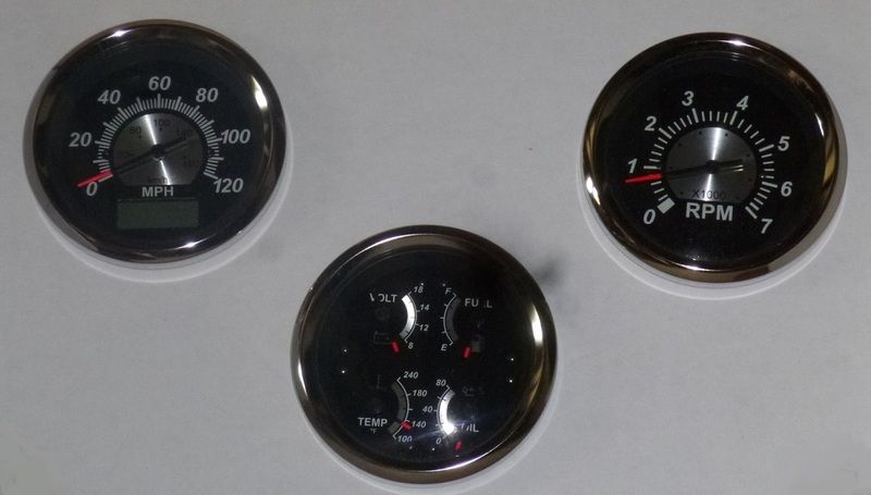
This is surprisingly one of the cheaper ways to get around the speedo issue with the ZF gearbox. Plus I'll have a different ratio at the rear end with the Jag 3.54.
The gauge set comes with GPS receiver and all other senders.
 
So I got a couple of well needed hours of work done on the car on Boxing day.
Firstly I made a start on my Jaguar diff installation, after over a year of building up parts and procrastination.
The rear mounting is going to be very similar to the California 5000tc design. I drilled the 2" box section to match the rear mounting points and cut down the spacers ready to weld inside. All bolted up nicely but I forgot to take photos, not that it would be very interesting at this stage.
Next I drilled the top 8x6" plate for the 4 top bolts. This plate will be welded to the box section to form the main mounting. Panhard rod has been stripped and will be used as per the Rover original design.

Here is the diff and various bits of the puzzle


The front of the diff will be supported and regulated by 2 ladder bars. These will attach to the diff with rose joints, and the rear crossmember with stainless rod end bushes, shown in the pic. The trickiest part will be clearance over the Jag handbrake calipers, which sit facing inwards and the linkage between of course.

The other thing I was desperate to get done was some progress with the hydroboost. I've now got it to a point where it's bolted up to the Rover master cylinder plate holes, with no modification to the base unit.
To do this I clocked the unit to where there was most clearance (very little!) and marked the mustang mounting plate. The way hydroboost mount to their brackets is a circular hole with a small internal tang to prevent rotation, along with the large securing nut at the rear of the plate. I cut the mustang plate to the shape of the rover master cylinder plate and re-drilled to suit. This is all temporary just to see if it is possible to fit it in the most obvious location.

Here it is bolted up, there is workable access to the rear spark plug but the unit is very close to the rocker cover, and two of the three lines will come out very near the headers. It still seems viable but I'm going to need to fabricate a nice heat shield for the lines. The master cylinder pictured is the mustang one and is clocked at 1 o clock to compensate for the mustang installation angle. I will be using an aftermarket dual master which will sit level, wilwood or more likely a CPP one which has a built in proportioning valve and brake ports on the underside to neaten up the look.


I plan to make an aluminium mounting bracket once I've finalised the fit etc.
The only annoyance is a niggle more than anything. If the engine needs to come out so will the hydroboost so the headers clear. Once I have everything how I want it, painted up and final fit it hopefully won't be coming back out again for some time!

Jim
 
Some more progress on mounting both the gearbox and diff.
The zf box when mated to rangerover bellhousing doesn't sit level as has been documented elsewhere on here.
My box is a volvo one and I began by making a rear plate from 3mm steel to counteract the angle.


Then I cut a plate to mount the bushing to


These were then welded together at 90 degrees with strengthening triangles, which fit in a recess between the mating face bolt holes not visible here


This had been my idea from the start but now mocked up I have decided to change the crossmember. I was going to weld spacer tubes with strengthening gussets and use these 5" bolts mounting up to the stock mounts. This just doesn't look right so I am going to create more of a cradle V shape with the rectangular box following the shape of the rear plate. The gearbox also may move up another half inch or so. I have trimmed one of the Rover stock mountings to allow it to fit with enough space around it.

Onto the diff mounting.
After wrangling it into position under the car, I have come across some errors in my earlier measuring.
Firstly it needs to move forward by 2" to line up with the hubs and upwards by another 2" so the prop will clear the V8 base unit rear cross member.
I'll use a slightly longer top plate 6x10 or 6x12 located on top of the box section to solve both of these problems.


image.jpeg

After unsatisfactory mocking up of gearbox mounting mark 2 I have had a good rethink and have settled on a simple design which will mean more clearance for exhausts. I have disregarded the rubber mount idea so it can sit higher. It will be a tubular crossmember with poly bushes at either end, attaching to brackets on the sides of the tunnel either welded or bolted.
More steel has arrived for the diff mounting as has the donor propshaft from a Jaguar 420 s type. I thought it was chunky and it sure is at 3.5" diameter!
I've also swapped my old bronze leather interior out in favour of a later thin backed black vinyl and cloth set which suit the build much better. The remaining interior will also become black, including carpet for a nice sleek look with polished details.
Jim
 
Last edited:
Finally all the measuring is done for my Jag IRS installation. I've cut and bent a new longer top plate, bolted to 2" box section ready for welding. Panhard rod will attach to two new tabs on an extended back plate. First view of the giant 3.5" Jag propshaft. Just starting to make the ladder bars now, the top links will sit further forward, lower and wider spaced clearing propshaft and handbrake caliper movement.
I'll be getting my 24mm Peugeot anti roll bar machined this week and also aim to finish the gearbox mounting. The latter I'm waiting on a 25mm former for my pipe bender so I can bend the tubular crossmember. This will have welded on poly bushes and bolt up to new tab mountings now I have removed the stock gearbox mounting brackets.


image_zpscvnyck2i.jpeg


Exciting stuff - it's good to see you're making progress and that your installation is progressing in much the same form as I have in my mind for mine. I'll continue to follow with interest :cool:
 
A very brief additional update which I forgot about.
It was an idea I'd had for a while now, involving led cob halo rings. The plan was to find ones small enough to fit the rear lamps.
I found 60mm ones which fit nicely in the lamp recesses after a little filing of the raised bumps.
I have red indicator lenses so bought amber rings for indicators and red for brake/running lights.
Here is the look mocked up through red lenses on the bench, they are very bright!


Jim
 
Long overdue update in which I'm sure to forget to include multiple things that I've done.
I only managed a couple of hours in the workshop today, but did make some progress.
Template cut for p38 starter motor flange to clock 90 degrees. This will be my first TIG welding project, under helpful supervision. I'll cut the new flange from 12mm aluminium plate.


My gauges have arrived


Progress with the Jag diff has been slow but steady. I've now cut and drilled all the plates for mounting and links and made a start on welding the ladder bar links.
I also have all the puzzle pieces regarding the handbrake: cable, both calipers, pads, spring forks, bolts etc etc..more money than you'd expect. I was waiting on setting up the handbrake calipers to confirm exactly how much movement and clearance is needed prior to welding on the top ladder bar links.
The handbrake cable itself is from an XJS but i'm having to shorten it. I have ordered a threaded swageless stainless fitting to reclamp the inner cable which will attach to a new stainless clevis for attaching the handle.
Clean up of the diff, prop and associated parts has also begun.


That will have to do for now. I'll update the update when I remember everything else!
Jim
 
Last edited:
Excellent stuff :)

I am very interested in the Jag diff conversion but am only at the gazing at pictures of Sparky's diff and the Jag one in the garage as yet. Couple of questions though, if I may.

Why the ladder bars?

Also, just from looking at Sparky's diff, the bracket that you have replaced with the box section is shaped to clear the discs on the Rover diff. Fitting a 2" box section across there will foul on the discs if the centre line is exactly the same with the jag diff fitted. Have you mounted the diff s bit further forward, or lower, or are the discs smaller?

Richard
 
Thanks Richard.
Ladder bars are my solution to keep the front end of the diff steady and secure, resisting twisting. I think the NZ race car has a similar idea, but with lengths of plate. Similar to the Rover extension tube being mounted on the rear crossmember. Stock exhaust clearance could well be compromised, but mine won't be stock..
Many jag irs installations use torque stay bars which triangulate from the lower front of the diff out towards chassis rails. I like the classic hotrod look of ladder bars too :D
If you scroll up some posts ago I had initially mocked up the box section on top of the plate as per Tom's 5000tc. This needed to move forward to line up with the hubs, and also upwards to make sure the prop would clear the V8 rear crossmember so I used a longer plate and mounted the box section on top to solve both issues. It is up as high as
I can get away with taking into account the ladder bar top links which are the highest point. This was the best compromise between pinion and gearbox output angles, whilst clearing all the neccessary components.
So to answer your question I think it's mostly that the jag unit is taller, ie the top face to centre of disc distance is larger so the discs are always going to be a little lower in relation to the mounting point..Unless you made the mounting location higher, but there's not much room to play with.
Jim
 
Cheers Jim

I see, that answers that then :). I haven't started formulating any designs yet, just some vague ideas of a similar box section with a longer plate, somehow rubber mounted to the small cross member and perhaps some sort of box construction around the diff.

I'll may just keep an eye on what others are doing and unashamedly steal their ideas :cool:

Keep up the good work, I for one am watching with baited breath

Richard
 
A very short time in the workshop tonight after a long day at work produced the starter motor hole cut.
73mm hole saw was rather hard on my tooling through 12mm aluminium even at a very slow pace.
Ideally this would be milled, something I'll be able to do soon as I'll have cnc milling capabilities :)
A quick clean up of the cut and this is the result. Bolt holes to drill next and the main template cuts, then it's ready to weld.


Jim
 
When I last said ready to weld, that wasn't strictly true.
After a couple of hours relieving the starter motor body and slot in the flange, it is actually now ready to weld!
If all goes to plan it will be one piece by this time tomorrow


Jim
 
Back
Top