rottenlungs wrote,...
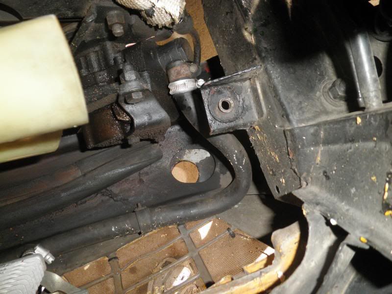
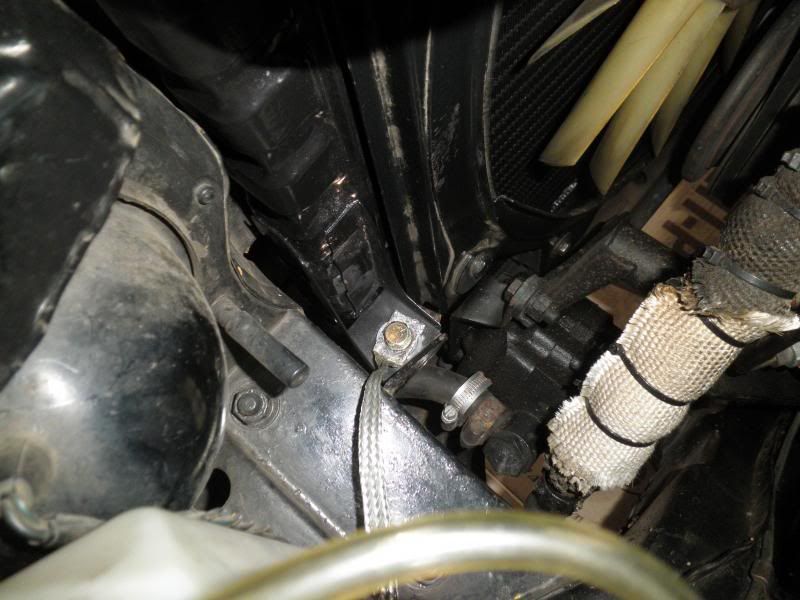
Thanks James.") What you describe could be down to the air control piston not moving as freely as it should. I fitted a NOS Lockheed kit that I had purchased some years ago, but in reality the only parts that need changing are the rubber seals within the slave cylinder. The gaskets between the slave cylinder and the vacuum chamber and between the slave cylinder and the air control valve can be made up. The diaphragm within the vacuum chamber is quite substantial and of excellent quality, so there should be no problem in using it again. It should be possible to match the seals with what is available at your local Brake centre. When you assemble it, use only brake fluid or very thin Girling grease (purple in colour) as a lubricant else the air control piston seal may stick and then the brakes won't come off any time soon.
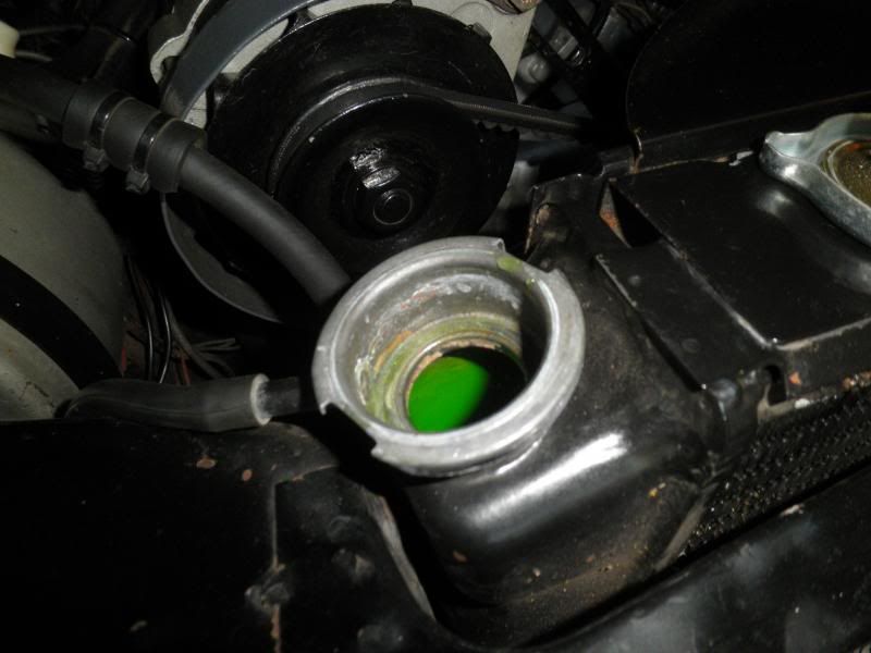
What you describe could be down to the air control piston not moving as freely as it should. I fitted a NOS Lockheed kit that I had purchased some years ago, but in reality the only parts that need changing are the rubber seals within the slave cylinder. The gaskets between the slave cylinder and the vacuum chamber and between the slave cylinder and the air control valve can be made up. The diaphragm within the vacuum chamber is quite substantial and of excellent quality, so there should be no problem in using it again. It should be possible to match the seals with what is available at your local Brake centre. When you assemble it, use only brake fluid or very thin Girling grease (purple in colour) as a lubricant else the air control piston seal may stick and then the brakes won't come off any time soon.
JVY wrote,...
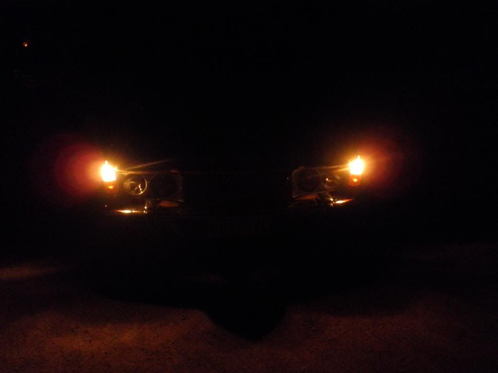
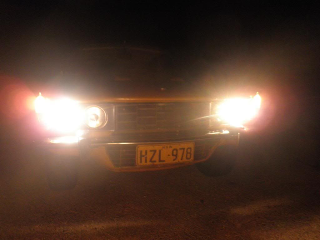
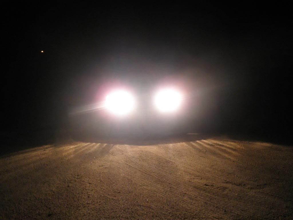
Thanks Steve,. Yes the 60W low beams are a big improvement over the original 37.5W sealed units. I'll post some night photos in the coming days, hopefully they will turn out ok. Glad you like my bug collection, every time I venture out I come back with more. I recall that an Entomologist can determine the type of insect by the splatter pattern that is left on the windscreen. Apparently, each is different.
Ron.
Ron
Top work on the booster - it looks sharp indeed with the drum painted.. With my car the booster is effective, but sometimes the pedal seems hard for a split second like a valve is slightly sluggish somewhere. If I tap the pedal it doesn`t really want to move, but if I apply a typical brake force, it works fine. As a result, I`ve been thinking about rebuilding it at some point soonish. Did you find the parts easy to get?
Thanks James.
What you describe could be down to the air control piston not moving as freely as it should. I fitted a NOS Lockheed kit that I had purchased some years ago, but in reality the only parts that need changing are the rubber seals within the slave cylinder. The gaskets between the slave cylinder and the vacuum chamber and between the slave cylinder and the air control valve can be made up. The diaphragm within the vacuum chamber is quite substantial and of excellent quality, so there should be no problem in using it again. It should be possible to match the seals with what is available at your local Brake centre. When you assemble it, use only brake fluid or very thin Girling grease (purple in colour) as a lubricant else the air control piston seal may stick and then the brakes won't come off any time soon.JVY wrote,...
Good mod Ron. I still have original sealed beams all round on my car. The full beam is OK (possibly brighter than some modern cars). However, the dipped beam is pretty miserable. So, I'm sure having two 55W dipped beams with coupled with modern halogen lamps, must make quite a significant difference.
BTW, good bug collection
Thanks Steve,.
Yes the 60W low beams are a big improvement over the original 37.5W sealed units. I'll post some night photos in the coming days, hopefully they will turn out ok. Glad you like my bug collection, every time I venture out I come back with more. I recall that an Entomologist can determine the type of insect by the splatter pattern that is left on the windscreen. Apparently, each is different.Ron.