Classicus, since we are both in NZ and can probably access the same sources for parts etc, I suggest we stay in touch over this. I'm in no great hurry to get the job done, but since I have the major components there I'm keen to eventually achieve PAS, for the same reasons you suggest. Although I live on the Canterbury Plains, it is likely that GF148 will be subjected to a certain amount of city driving, and as you will know, spinning that hefty wheel around car parks isn't much fun. Having driven a PAS example in the past I also know just how delightful the conversion makes a P6B.
My aim now is, with the help of other contributors to this thread, to put together the definitive list of parts required to complete the conversion.
Confirmed so far:
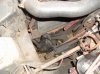
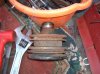
PAS steering box.
Reservoir.
Pump.
Mounting bracket.
Pulley (and belt).
Unconfirmed:
Drop arm.
Track rods.
Wiper mechanism.
Please add/modify/correct this list as required.
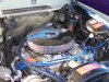
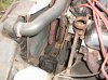
Also, can anybody put up a photo of a PAS engine bay so that we non-PAS blokes can get an idea of where all the components sit?