DOHC Daily Driver.

Hi, I am on a late shift this week so I have time to start pulling the engine out of the Rover. An hour or so later the engine and box were out and on the floor.
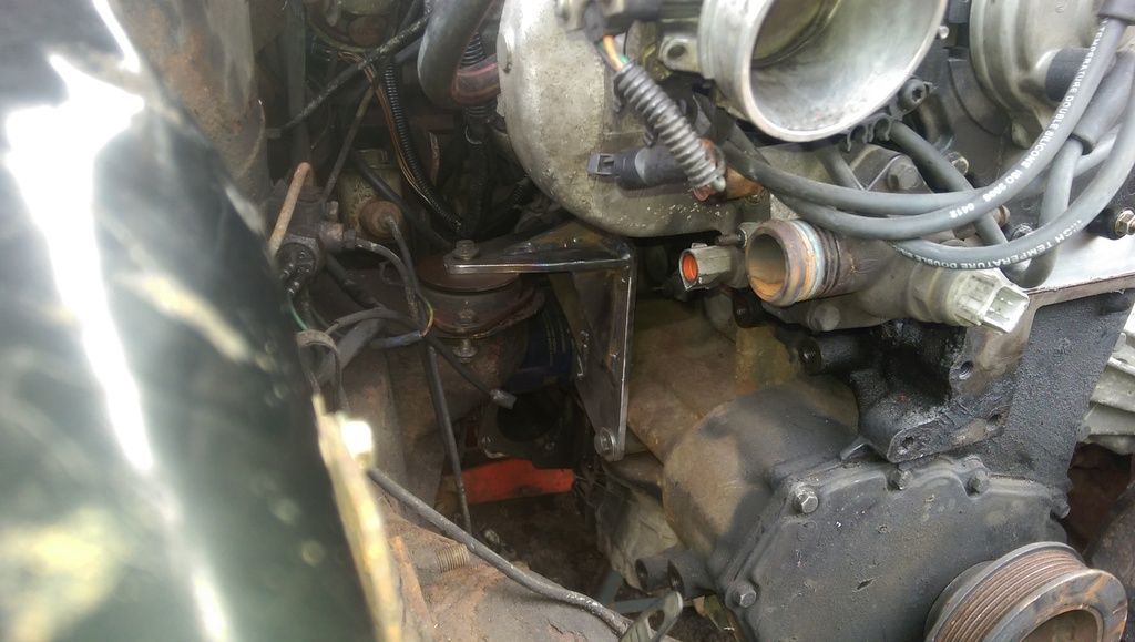
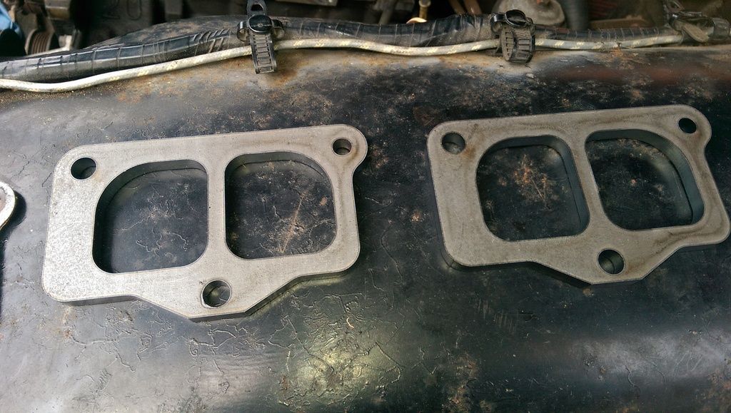
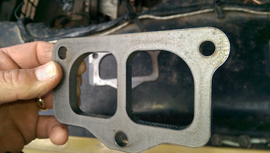
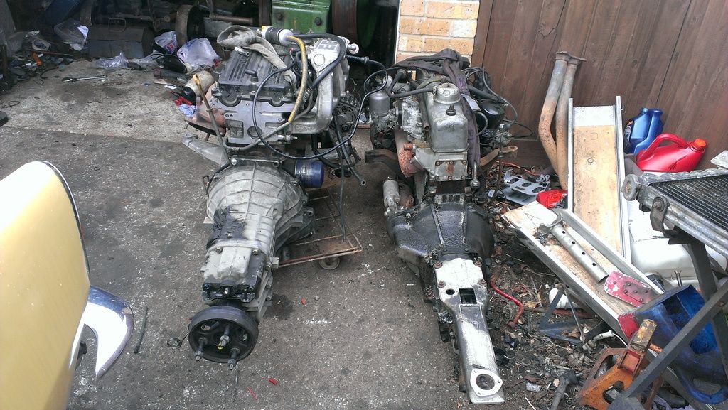
I placed the new engine next to it as a comparison for length etc, the difference in the widths between the two cylinder heads can clearly be seen!
IMAG1829_zps1wilvmec.jpg

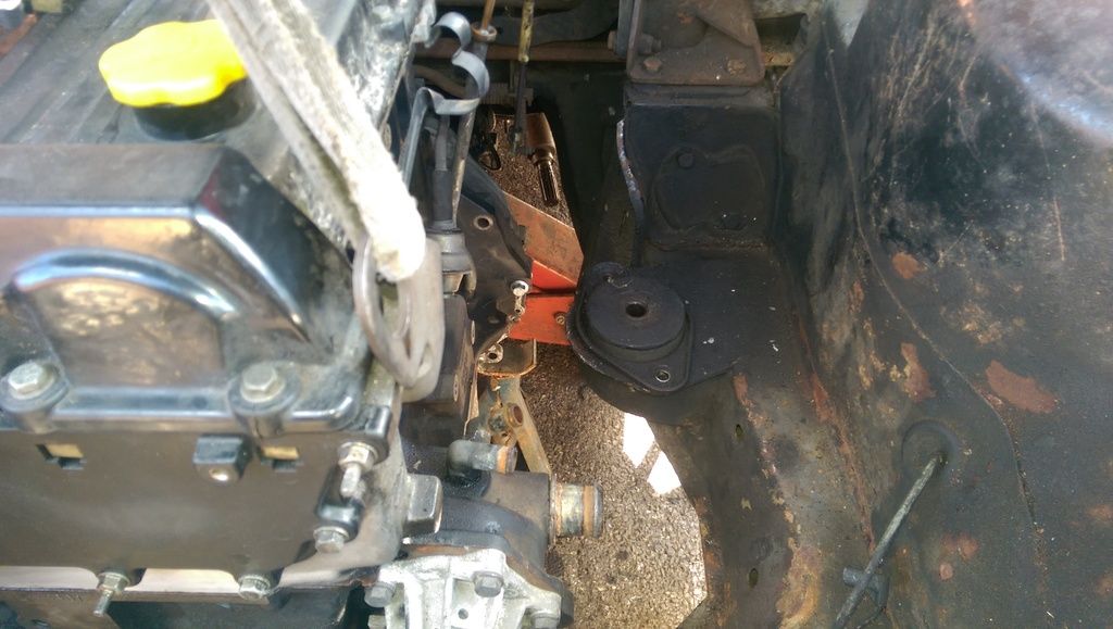
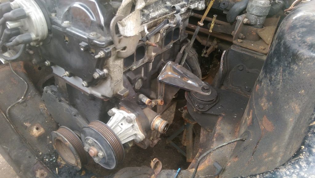
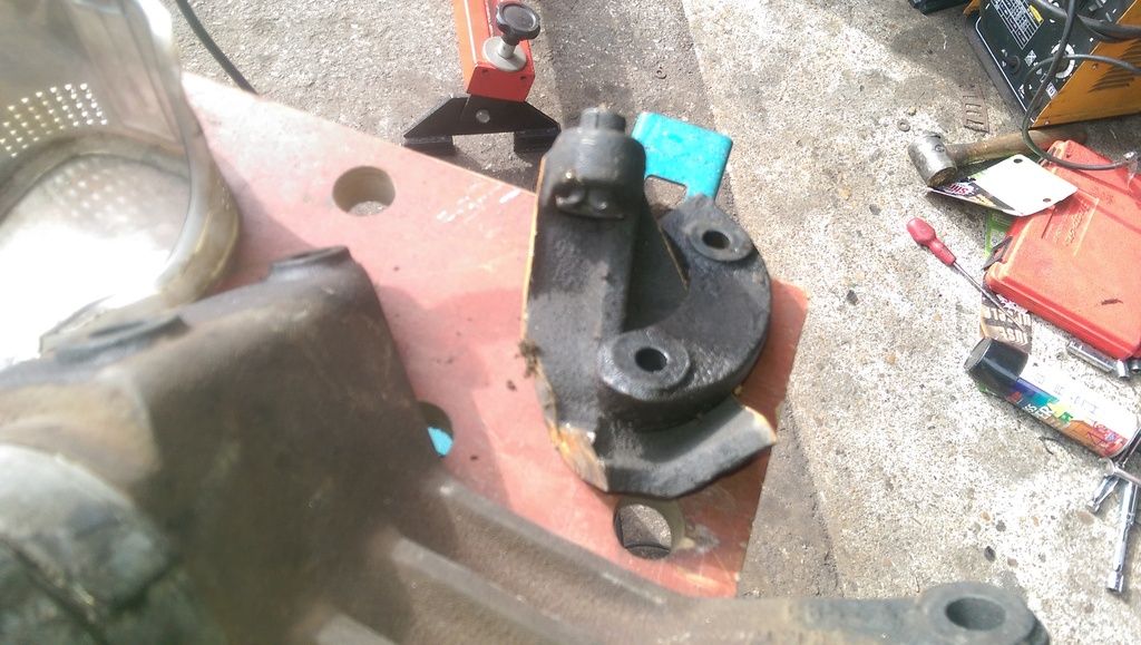
With that out I decided to see if the new engine would come even close to fitting. My heart sank as the gearbox became firmly wedged in the brackets for the back mount, I do not want to start cutting lumps off my car and I want to do this conversion in such a way that it would be possible to return it to standard, that said, I have accepted that I may have to remove the original engine mounting brackets, this shouldn't be too bad as they look like they are spot welded on and will hopfully come off reasonably intact.
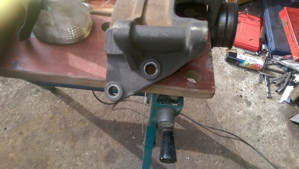
The gearbox issue turned out to be the large vibration damper fitted to the output spider being too big to fit through, I am doing away with the guibo joint and am going to run a normal UJ so this was quickly removed. This allowed the gearbox to slide in between the mounts :D The engine does fit...just. I have got to cut the PAS pump mount of the alternator bracket as it fouls the cross member, this will be done on Wednesday if I get the time.
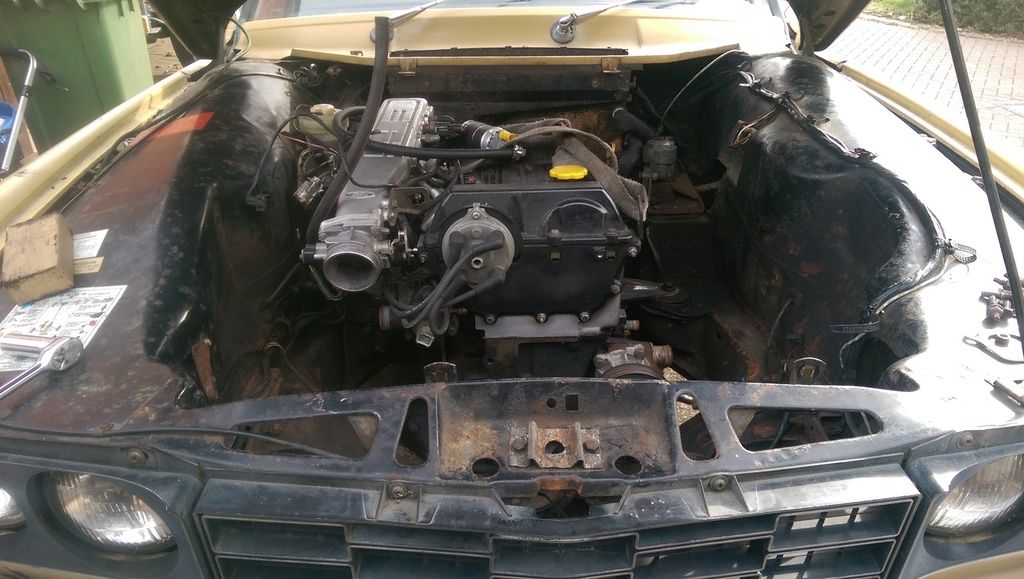
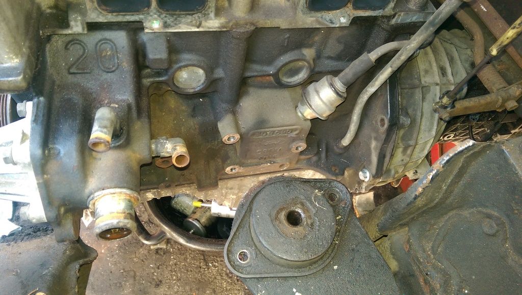
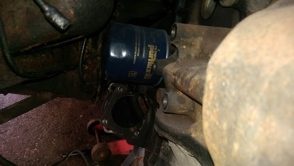
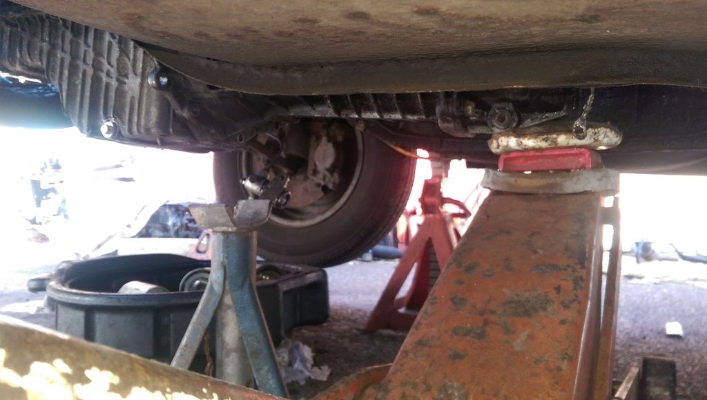
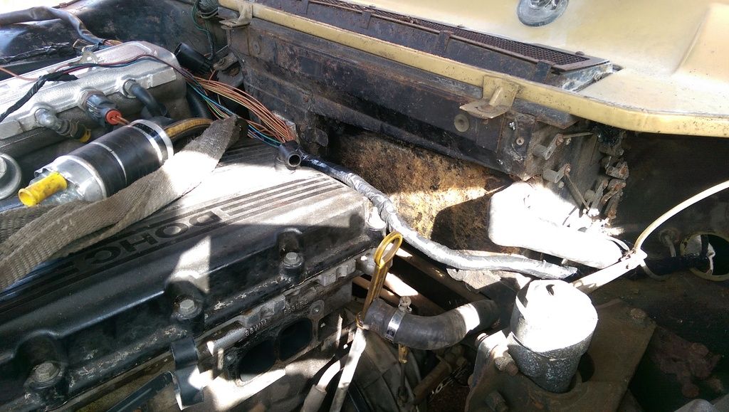
Here are a couple of pictures of the new engine just sitting in the "hole" Obviously it has no mounts!!!!!!

IMAG0303_zpsula8wgs7.jpg


IMAG0305_zpsemamf5qe.jpg


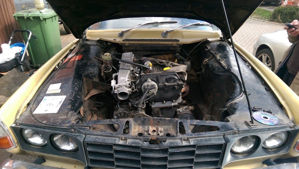
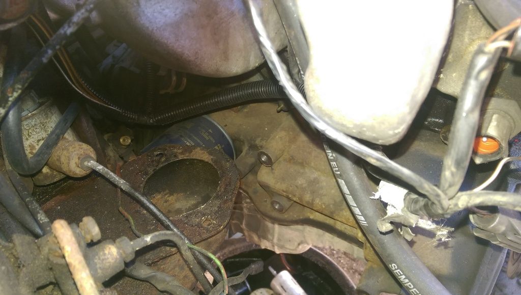
Check out how much room there is at the front!!!!!

IMAG0306_zpsiuts2yvw.jpg


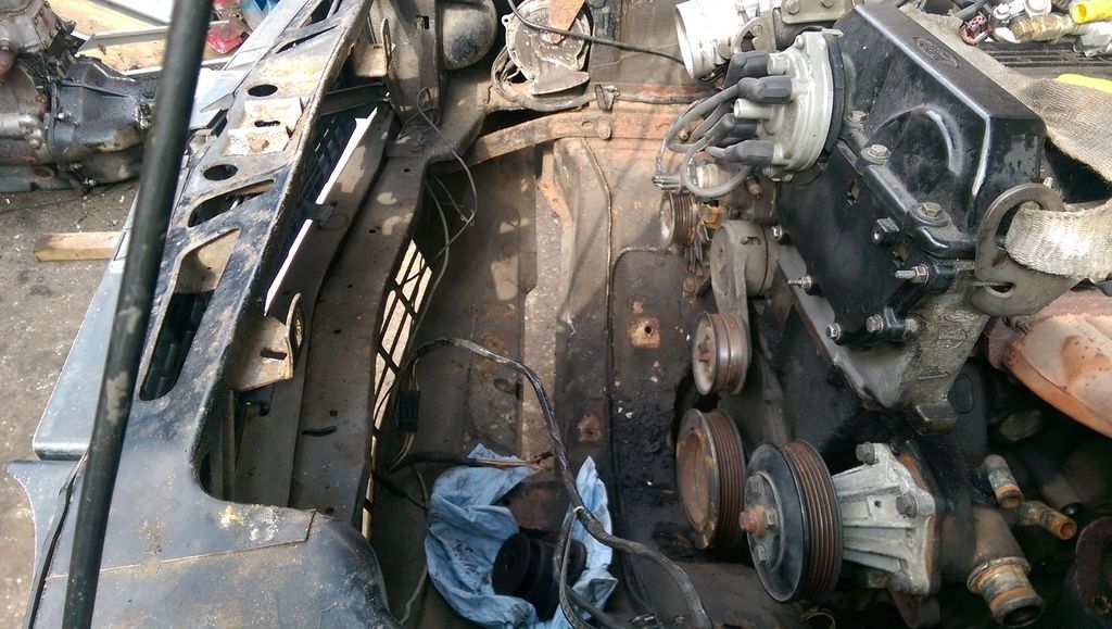
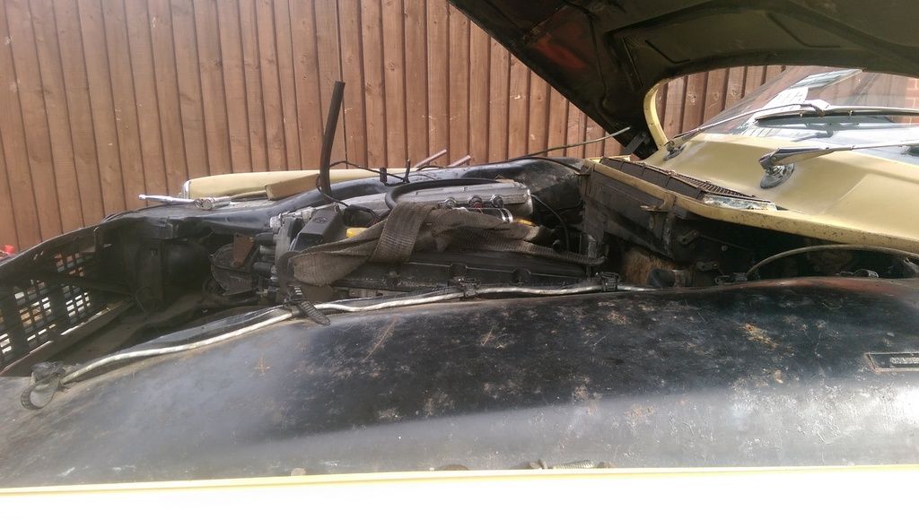
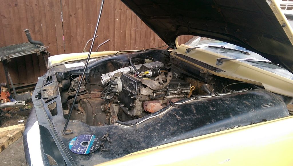
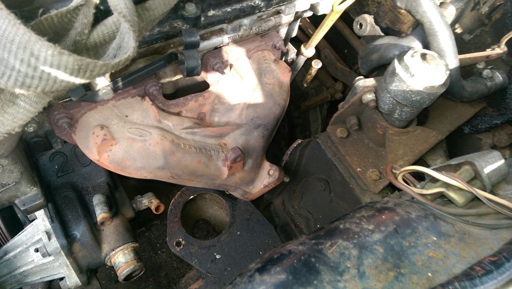
I am really hoping that I will be able to thread the exhaust down through here somehow.

IMAG0307_zpszjrolsbr.jpg


I am just so pleased that it fits in there at all, I was worried as it is certainly a lot wider than the original engine at the top ans the gearbox is certainly much bigger!

Dan
 
Looks like you may need a new exhaust manifold fabricated to wend your way thru.

Graeme
 
ghce said:
Looks like you may need a new exhaust manifold fabricated to wend your way thru.

Graeme


You are spot on with that, I have decided to ditch the original cast iron manifold. Today was spent determining the final positioning of the engine, now that I have settled that I will start fabricating the mountings. I will be using the original mounting brackets on the body as with the exhaust manifold gone there is now plenty of room.
IMAG0310_zpsc632tbdi.jpg


IMAG0312_zps8whgddli.jpg


I will be hopfully getting a couple of flanges laser cut so that I can start making a manifold, I have bought a tubular manifold off ebay that will be cut up once it arrives. I have a plan of where it will fit in my head, hopefully I will be able to replicate it in the metal!
There is a bit of a clearance issue on the OS between the inner panel where the reserve tap is and the oil filter....

IMAG0308_zpsj9pqzaul.jpg

The tap will be pulled out soon and a shallower Cosworth oil filter fitted so that one is easily sorted.
The mount for the OS should be ok to make.....

IMAG0313_zpsnhdyxfxj.jpg


Here are a couple of under car shots to show how it fits, I'd say it has slotted in rather well.

IMAG0318_zpsrnlaj22c.jpg


IMAG0319_zpsnj3kc6gc.jpg


The back mount for the gearbox has lined up almost perfectly with the original brackets, how lucky is that?? and as I thought the remote gear linkade will have to be lopped by around two inches to line up but that should be easy because it is made from pressed steel.

Dan
 
drabbers said:
That's a really interesting conversion.
Keep up the good work.

Mark.

Thanks Mark, I appreciate that. I have roughed out the plates for the engine mounts tonight and weather permitting I hope to get them shaped and tacked together in the morning. My mate will be doing the final welding as my welder is not really man enough and moreover, he is a far far better welder than I will ever be!!!!!!!!!!!!

Dan
 
Hi, The weather was foul this morning but in between showers I managed to get the engine mount brackets roughed out and tacked together ready for my mate to do a proper job of welding them later. I have gusseted them for extra strength.

IMAG0321_zpscicbkv8e.jpg


IMAG0323_zpsrim9ofje.jpg


Please excuse the pigeon poo, my welder isn't really up to the job, especially in the wind.
The other thing I got done was to sort out the exhaust manifold flanges. I left an exhaust manifold gasket with a local laser cutter, they are going to make them out of 10mm mild steel so they will be plenty strong enough, they should be ready on Monday so once the ebay manifold arrives I will be able to crack on with the exhaust.

Dan
 
Hi, Here is this mornings progress.
The mounting brackets were properly welded yesterday...........slightly better than what I did!, I finished off their final shape before test fitting them to the engine.
IMAG0325_zpscmqel7cp.jpg


They fitted absolutely perfectly. :D
OS
IMAG0327_zpspidzbo7k.jpg


And the NS

IMAG0326_zps4mgdntsd.jpg


This is how the engine sits on its new mounts..
IMAG0328_zpsyxoik9ly.jpg


IMAG0329_zpsngzd26hj.jpg


I think it sits in there very well. The other job I have been looking at is the alternator bracket. This originally also held the power steering pump but would never come close to fitting with that still on
I have now completely removed the pump and its mounting.

IMAG0331_zpshv55hwps.jpg

IMAG0330_zpshrhexgyq.jpg


Even with that lot removed I may still have to relieve the front cross member slightly to make enough room. I will know for definite once I have finished off the gearbox back mount. That is tomorrows little project.

Dan
 
That looks really good so far. I'm slightly concerned with your engine mounts though. The mounting plates you've had made up look strong enough but the welds on the biggest support fillets are in tension with the bulk of the plate lower than the mounting point. I'd be happier if the plate was the other way round and mostly in compression. Have you had one tested to destruction to see how much tensile stress the joints will withstand?

Have you considered upgrading the engine mounts to the VW mounts as discussed elsewhere on the forum?

Keep up the good work.

Dave
 
Hi, I think you are worrying unnecessarily Dave. Those look more than strong enough, I have seen
manufacturers use thinner steel than that in similar mounts. The fillets under the horizontal do more
than support it, they also stop the vertical from bending in towards the block and the fillet above the
horizontal is helping as well. In the the pic of the two engines compare the engine brackets, the Ford
one is made of Aluminium as opposed to the Rovers forged steel spiders legs. The Ford engine is I'm
guessing lighter than the Rover one because of Fords use of thin wall blocks. Most people who do this
sort of thing don't have the luxury of destruction testing so that's why they tend to be overengineered.
If it was, I would think the horizontal between the top fillet and the hole would bend first. Personally I
might have thought about having the horizontal underneath the mount, but that would only be to use
less material. But that may cause problems with the routing of the exhaust. Lots of things to think
about, but well executed so far.

Colin
 
Hi, I had a call from the laser cutters today to tell me that the flanges are ready, unfortunately my sacrificial manifold has not turned up yet so the manifold is still on hold. The gearbox back mount metal work is complete, all I need is a new mounting block. One good thing that doing this rework has shown up is an ailing servo. I removed it when fitting the new engine and I laid it on the floor whereupon it rolled over and proceeded to deposit a reasonable amount of brake fluid out of the vacuum connection. I had no idea it was leaking internally so a rebuild kit has been ordered for it.
Does anyone know where I can get a throttle pedal grommet from please? Mine has all but disinterested!

Dan
 
hi, I have been reading ur thread with interest. as to a throttle peddle grommet have u tried wins international or mark grey
many thanks
coop
 
Thanks mate, I will get on on order. I collected the manifold flanges today, they are absolutely superb!, they would have taken me many hours to do myself manually!

IMAG0348_zpst40dvnnr.jpg


IMAG0349_zpslvlkcg4i.jpg


I am well pleased with these! All I need is for the manifold to turn up :evil:

Dan
 
Like it===But are you afraid to cut bits in bay ? just thought you would get more room if you cut old mounts and made your own up==
Be different mate-why should cars be the same -people aren't
 
Hi, I have now sorted the engine mounts, I really do not want to cut the shell about..........after all, if I hit an impossible obstacle later on during the conversion I could always refit the original engine, if I destroyed all the original mounts that would be quite difficult.

Dan
 
Hi, Still, the manifold has not turned up! I chased the seller up through the ebay messages and he has assured me that it has been sent out.........hmm, I'm not convinced! Anyway, his reluctance in sending it out is delaying me somewhat. I really need to make the manifold before I can remove the engine and box assy to allow me to sort the clutch and throttle pedal conversion.
Without the manifold I decided to see if the EEC IV management wiring loom would be long enough to reach the engine with the module sited where I want it to go in the glove box. First job was to tidy it up a bit, I re taped the main wiring, it looks ever so slightly better now. I left a section untaped, just in case I needed to extend it.

IMAG0363_zps6tem58jk.jpg


This is the grommet hole that will be taking the engine loom......it it big enough???
IMAG0365_zpskpidkbvh.jpg


Initial impressions were less than encouraging....
IMAG0366_zps4tp0jvdd.jpg


Fortunately, the loom is thin enough to pass through the baulkhead from the other way, the larger multiplugs only just passed through. The loom will be attatched to the original throttle rod and choke cable brackets and will be fixed to the heater box as it runs behind the cylinder head, It will be mounted on the inner wing to mirror the existing wiring on the NS.
IMAG0367_zpsgxo1nged.jpg


With the loom laid in the engine bay and the module connector where I want it, the main connectors easily reach those on the engine. I am well pleased about this as although I was happy to alter the length of most of the wiring the crank sensor wiring is shielded from module to sensor. I didn't want to have to chop and mod this, fortunately I didn't have to!
IMAG0368_zpswhuxivzq.jpg


The existing coil has now been removed, it is totally useless in this application as it is ballasted, there is more room down the OS now.
IMAG0369_zpscedcky63.jpg


The new coil and TFI module wiring will need modifying though........it reaches five feet out from the front of the car!!!!
IMAG0370_zps1ekhyylt.jpg


Here is what I am going to have to connect up inside the car. The yellow relay you can see is for the engine cooling fans.
IMAG0371_zps9ygkakgl.jpg


This is how the previous owner had wired in the rev counter to the coil.....
IMAG0373_zpstulhdqze.jpg

There is a dedicated wire for the tacho in the engine loom so I wire it into that........properly!

Dan
 
Fascinating thread. Great pictures. Reminds me what a spectacular lack of effective soundproofing a P6 has on the bulkhead compared to a modern despite the inch-thick carpets.
 
Back
Top