DOHC Daily Driver.

PeterZRH said:
Fascinating thread. Great pictures. Reminds me what a spectacular lack of effective soundproofing a P6 has on the bulkhead compared to a modern despite the inch-thick carpets.

Cheers mate!
I had a little delivery today :D
IMAG0376_zpss8j8ltkk.jpg

IMAG0378_zpsmx1crxqs.jpg


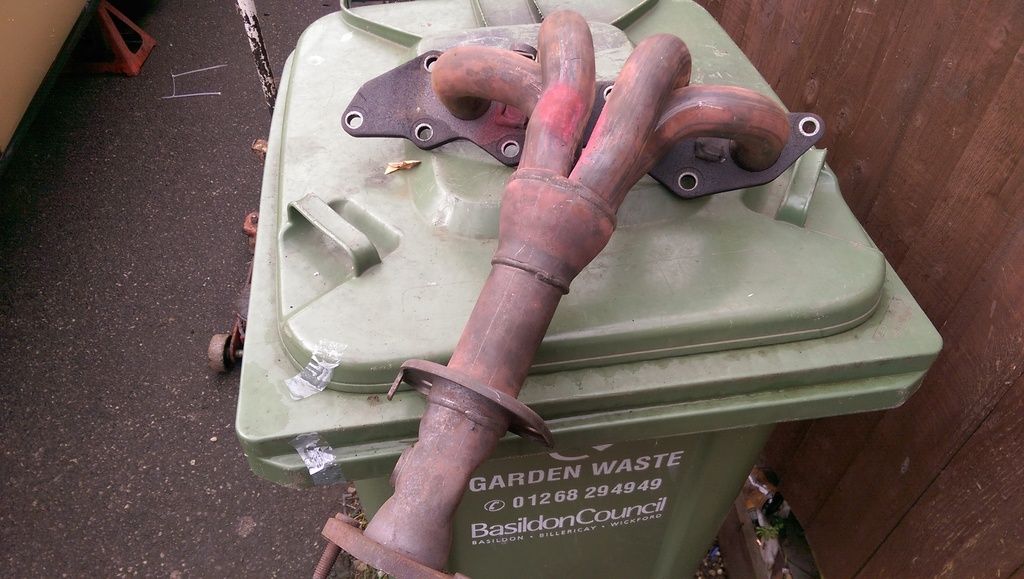
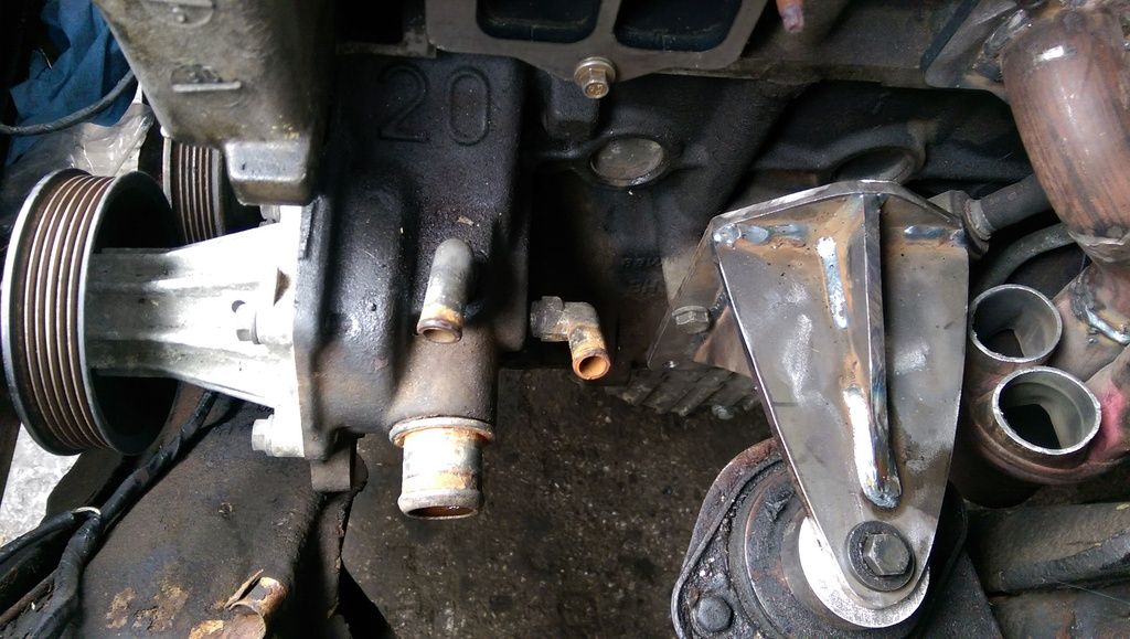
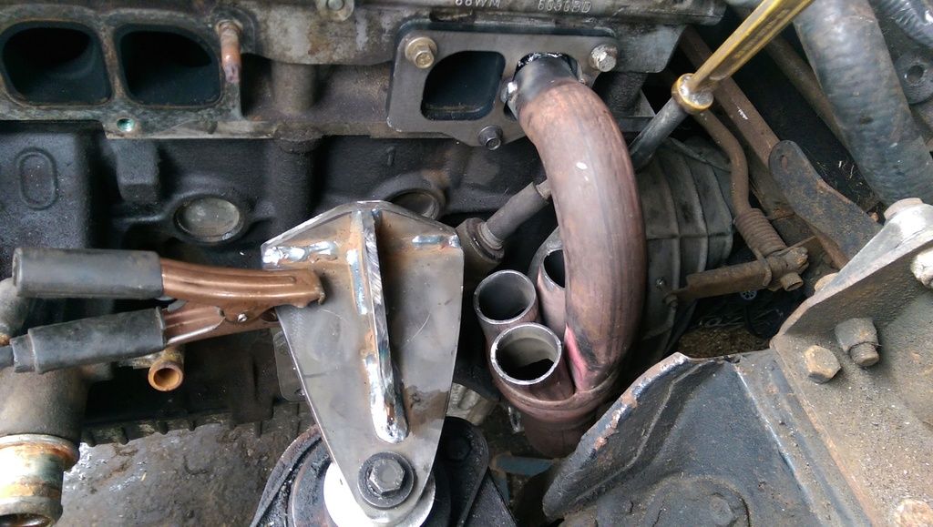
The first job was to remove the flange plate.
IMAG0379_zpsyb6zlefe.jpg


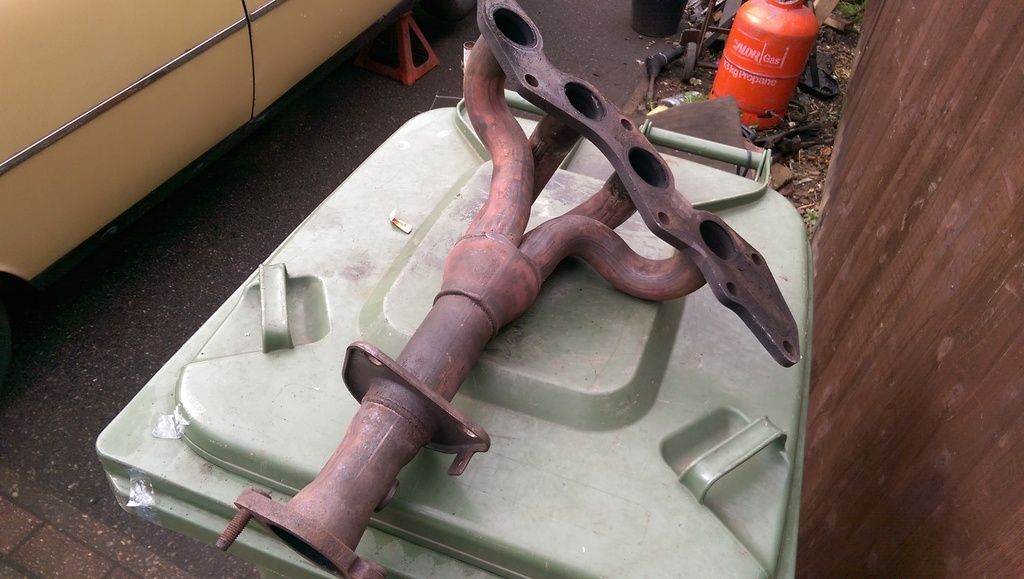
It was then offered up to the engine to see if anything would line up or not....unsurprisingly, not a lot did.
IMAG0382_zpsldrl4efu.jpg


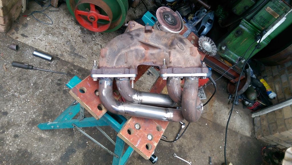
Three if the primaries were cut off just above the collector, the new manifolds original No2 runner is now my No4, it was offered up and then tacked onto the flange.
IMAG0383_zpst19ikniq.jpg


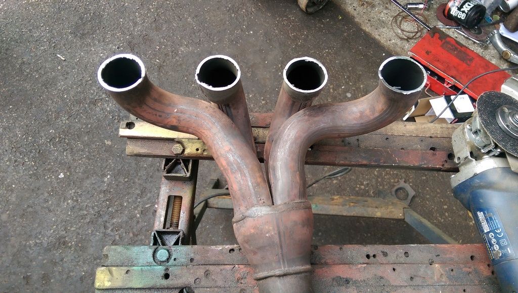
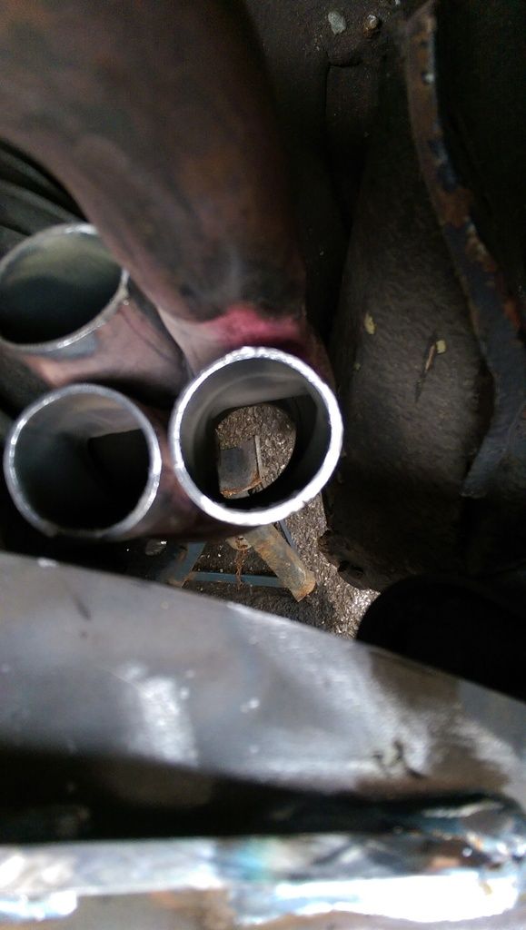
A view through the collector, I have angled it back slightly, there is enough room for a single down pipe to pass between the NS chassis rail and gearbox.
IMAG0385_zpsw6mnwapv.jpg


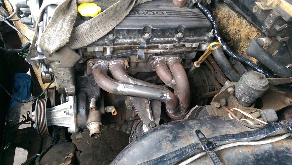
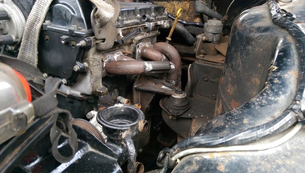
I cut and shut one of the other primaries to create a runner for N03, this was then welded up leaving me with this.
IMAG0386_zpse35k1uqr.jpg


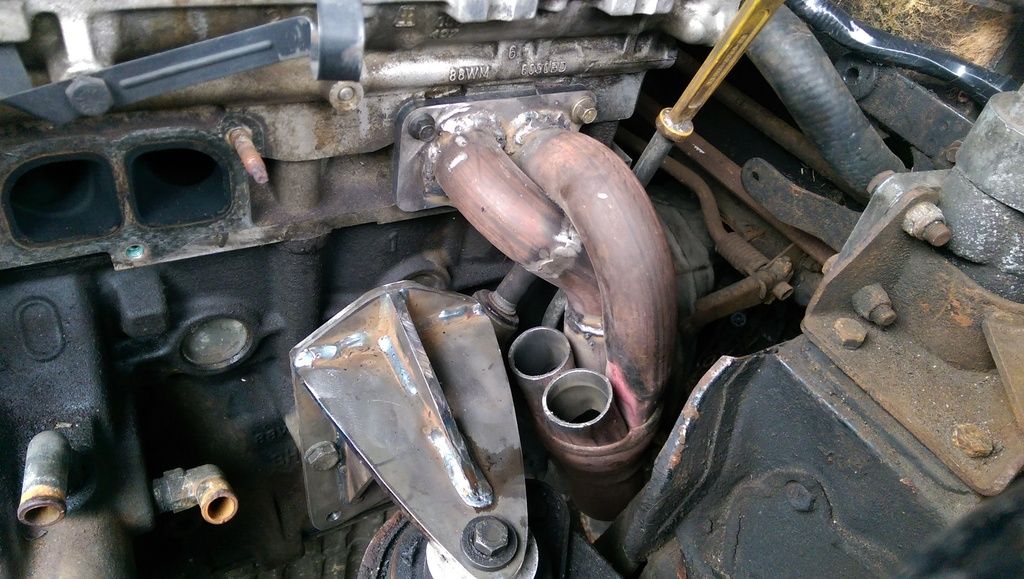
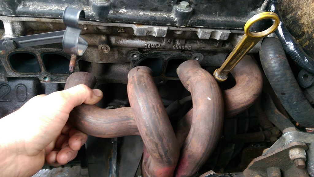
I have a couple of bends left but I am short of suitable pipe, hopefully I will be able to find a supplier tomorrow so that I will have the primaries finished leaving only the
down pipe to do. Runners 1+2 will be a fair bit more awkward than the ones that I have done, still I am pleased to be as far on with this as I am.

Dan
 
cooper1203 said:
was just about to ask doesn't the headers have to be equal lengths
coop

AS others have said, ideally all runners should be of equal length but the cast iron manifold that I removed was hardly the last word in efficiency as all runners were unequal and there were two T intersections!

Dan
 
danm said:
cooper1203 said:
was just about to ask doesn't the headers have to be equal lengths
coop

AS others have said, ideally all runners should be of equal length but the cast iron manifold that I removed was hardly the last word in efficiency as all runners were unequal and there were two T intersections!

Dan
Really ? the cast one you took off had more equal lengths than one your making and looks like it had larger outlet at mounting flange too - I just hope it works ok for you
 
The inner pair of the old manifold that served 2+3 run inside those for 1+4 so are definitely a shorter. I hope it works too, at the end of the day, I have got to work with what I've got and the space available. :oops:

Dan
 
well if a problem loop 3+4 header pipes =you got room for that--if needed -- this is intriguing me--as am sure many others are too--I would bite the bullet though and if bay needed chopping--then so be it--if you keep thinking-if it dont work put it back----dont do anything mate---However now you getting into it--think 3 steps ahead at all times otherwise something will give you a brainache == keep at it now--cant wait for next progress update 8) 8)
 
hi, I was thinking u were going to run 1+2 one side of the mount and 3+4 the other side and join them in the middle. dunno where I got that from though must of dreamed it
coop
 
that would work -if room available --- or even pipe through engine mount--I cant wait for youtube of this baby going --make a change to v8s 8)
 
cooper1203 said:
hi, I was thinking u were going to run 1+2 one side of the mount and 3+4 the other side and join them in the middle. dunno where I got that from though must of dreamed it
coop


That was my first thought also when I saw the pictures.

Graeme
 
Brilliant work, nice to see a different and reasonably sensible engine going in, would be interesting to see the difference with handling/ performance, do you know the weights of the different lumps?
 
herbie said:
Brilliant work, nice to see a different and reasonably sensible engine going in, would be interesting to see the difference with handling/ performance, do you know the weights of the different lumps?

Cheers mate :D
I did consider routing the runners each side of the engine mounting but the positioning of these water inlets made that option awkward.
IMAG0388_zpsedi9y18g.jpg


I have now finished mt manifold. I am pleased with how it has turned out............even though the runners are not all the same length! I tacked the primaries into position on the engine and used the original cast iron manifold as a jig/heatsink to prevent/reduce the possibility of distorting it as it was welded together.
IMAG0390_zpshxhqqisy.jpg


The finished manifold on the engine.......
IMAG0391_zpsjk9bcy6c.jpg

IMAG0392_zpsoxqqqlv2.jpg


Next on the list is the down pipe and then the gear change remote.

Dan
 
symes said:
when this works--whats next---turbo?? Love it ! glad to see your progress-- 8) 8)

Thanks mate....turbo, now that's a project for another day! Would be good though!

Dan.
 
Love it----come on finish-----want to see this beat the doubters 8) 8) make the outside completely stock and a nice shiny paint job :D :D
 
What doubters? This will be good... P6s do lack 5 speed gearboxes so this will be a nice drive i think?
 
Nice work. You make an engine / gearbox transplant appear easy!
With a lighter and more efficient engine and a 5 speed gearbox i have no doubts that the driving experience will be transformed, but on a personal note i find a little hard to swallow a Ford engine in a Rover P6!

I did notice that you used spacers to raise the engine a little over its mountings in comparison with the early photos, did you do this to help locating the exhaust?
 
Hi thanks mate, I have fitted some spacers to lift the engine up as I had not allowed enough clearance for the alternator, with them fitted, the alternator slots home ok.
I can kind of understand where you are coming from with your comment about a Ford engine............
The DOHC mill weighs 134 kg without the clutch. I do not know how much the original unit weighed, only that it felt heavier than what I am fitting.

Dan
 
did anybody say about ford in rover with the 302 v8 put in a 3500 ? better a ford than bmw eh - considering what happened to rover
 
Back
Top